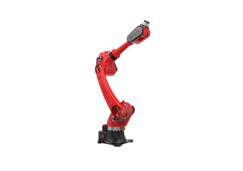
BRTIRUS1820A Robot Cell for Bar and Rod Feeding: Reach, Gripper Clearance, Payload and Cycle Time


Why bar and rod feeding is a reach problem before it is a robot problem
Bar and rod feeding looks simple on a process sheet: pick a bar from a stack or magazine, present it to the next operation, repeat. In practice, most feeding cells that underperform are not limited by the robot's speed or repeatability — they are limited by geometry. The robot has to reach the pick point, clear the gripper and the bar over the magazine wall or adjacent bars, and present the bar at the correct orientation without the tail end sweeping into the feed table.
This guide is written for procurement engineers who are specifying a cell around the BRTIRUS1820A six-axis robot. It walks through the four variables that decide whether the cell works: reach envelope, gripper swing clearance, payload per cycle, and the feed table layout that sets cycle time. The robot's published figures are the starting point; the cell design around them is what determines throughput.
The customer problem: bars are long, magazines are crowded, and the gripper is wider than the bar
Consider a manufacturer feeding steel bars into a downstream process — a saw, a press, a heating station, or a machining centre. Typical constraints look like this:
- The bar magazine sits at floor level or on a low stand, and the pick point is offset from the robot base.
- Bars are stacked in layers, so the pick point moves up and down as the magazine empties.
- The gripper holds the bar near its centre of gravity, which means the bar extends well beyond the gripper jaws on both sides.
- The bar has to be lifted clear of the layer below before it can travel to the presentation point.
- The presentation point is usually at a different height and angle from the pick point.
Each of these is a geometric constraint, and each one consumes reach. A cell that is designed only on the nominal working radius — without accounting for gripper width, bar overhang, and lift height — will pass simulation and fail on the floor.
Why automate bar and rod feeding at all
The case for automation here is not about replacing people for its own sake. It is about the four things that manual bar feeding struggles to deliver consistently:
- Repeatable presentation. A bar presented at the same position and angle every cycle removes a major source of downstream variation.
- Stable output over a shift. Manual feeding pace drifts; a robot cell holds its cycle time.
- Predictable part handling. Consistent grip position reduces damage to bar ends and to the gripper itself.
- Flexibility across batch sizes. A programmable cell can switch between bar diameters and lengths without mechanical changeover, provided the gripper and magazine are designed for the range.
For heavy or long bars, there is also an ergonomic argument: manual handling of long steel bars is physically demanding, and the handling quality degrades over a shift.
Solution logic: what an integrated feeding cell actually contains
A bar/rod feeding cell is a system, not a robot. In an integrated configuration, the pieces that have to be designed together are:
- Robot and controller — the motion platform and its programming environment.
- End effector — gripper type, jaw opening, grip force, and grip position along the bar.
- Bar magazine / feed table — layer height, layer pitch, separation between bars, and the mechanism that indexes the next bar or layer into the pick zone.
- Presentation fixture — the downstream pick-up point, including any orientation or centring feature.
- Safety and guarding — perimeter fencing, light curtains, and interlocks sized to the cell's actual reach envelope, not the robot's nominal one.
- Control integration — handshake between the robot cell and the downstream machine, so that the robot does not present a bar into a station that is not ready.
The engineering work that matters is the interface between these parts. The robot provides reach, payload, and repeatability; the cell design decides whether those figures are usable.
Key selection factors
1. Reach envelope — and what eats into it
The BRTIRUS1820A is a six-axis robot with a published arm reach of 1,895 mm and repeatability of ±0.05 mm. Those are the headline figures, and they are the right place to start. The question for a feeding cell is how much of that reach is actually available at the pick and place points.
Reach is consumed by:
- Gripper offset. The distance from the robot's wrist flange to the grip point is not free. A long gripper body or a gripper mounted on a spacer reduces the effective working radius.
- Bar overhang. If the bar is gripped at its centre, half the bar length extends beyond the grip point. The robot has to carry that overhang through the whole transfer path.
- Lift height. Clearing the layer below requires vertical travel at the pick point, which is often at the edge of the reach envelope rather than the centre.
- Presentation angle. If the downstream station requires the bar at an angle, the wrist has to articulate, which changes the usable reach.
A practical approach is to plot the pick point and the presentation point in the robot's working envelope, then add the gripper offset and the bar overhang as offsets from the wrist flange — not from the robot base. If both points plus the lift clearance fit inside the envelope with margin, the reach is adequate. If either point sits near the boundary, the cell layout needs to move, not the robot specification.
2. Gripper swing clearance
Swing clearance is the constraint that catches feeding cells late in the project. When the robot rotates the wrist to orient the bar, the gripper and the bar sweep through an arc. If that arc intersects the magazine wall, the adjacent bars, the presentation fixture, or the safety fence, the cell cannot run at the programmed orientation.
Three clearances need to be checked separately:
- Gripper body clearance — the physical envelope of the gripper as the wrist rotates.
- Bar sweep clearance — the arc traced by the bar ends, which is much larger than the gripper envelope for long bars.
- Retract clearance — the path the robot takes when withdrawing from the magazine after a pick, which is often the tightest move in the cycle.
For long bars, the bar sweep is usually the governing constraint. It is worth modelling the bar as a rigid body through the full transfer path, not just at the pick and place points, because the mid-transfer orientation is often where interference occurs.
3. Payload per cycle
The BRTIRUS1820A has a rated payload of 20 kg. In a feeding cell, the payload calculation is not just the bar weight:
| Item | Typical contribution | Notes |
|---|---|---|
| Bar / rod weight | Varies with diameter and length | The dominant term for solid steel bars |
| Gripper assembly | Fixed | Includes jaws, body, and any mounting adapter |
| Gripper mounting offset | Fixed | Counts toward the moment load even though it is not a mass at the flange |
| Cable and hose package | Small but non-zero | Routing affects the moment arm |
| Dynamic allowance | Application-dependent | Acceleration and deceleration loads add to the static weight |
The rated payload is a static figure at the flange. What matters in practice is the moment load — the combination of mass and distance from the flange. A long gripper holding a bar at its centre of gravity creates a moment arm that is much larger than the bare payload figure suggests. When the payload is close to the rated value, the moment load and the acceleration profile both need to be reviewed against the robot's load curves, not just the headline number.
A sensible design rule is to keep the combined gripper-plus-bar mass comfortably below the rated payload, and to keep the grip point as close to the flange as the application allows. For heavy bars, gripping closer to one end reduces the moment arm but increases the overhang on the other side, which feeds back into the swing clearance check.
4. Feed table layout and cycle time
Cycle time in a feeding cell is set by the slowest element in the chain, and that is rarely the robot's transfer move. The feed table layout usually dominates:
- Layer indexing time. If the magazine indexes one layer at a time, the robot waits during indexing. If it indexes per bar, the wait is shorter but the mechanism is more complex.
- Pick point travel. The distance the robot travels from the presentation point back to the pick point is part of every cycle. A magazine placed close to the presentation point shortens it.
- Bar separation. Bars that touch each other require a separation move before the grip closes, which adds time and can cause jams.
- Gripper actuation time. Opening and closing the gripper is a fixed cost per cycle; a gripper sized for the largest bar in the range may be slower on small bars.
- Downstream handshake. If the robot has to wait for the downstream station to signal ready, that wait is part of the cycle.
The layout decisions that most affect cycle time are the distance between the pick zone and the presentation point, and whether the magazine can pre-index the next bar while the robot is transferring the current one. A magazine that pre-indexes during the transfer move effectively hides the indexing time; one that indexes only after the robot has returned exposes it in every cycle.
A useful comparison for procurement is the difference between a single-station magazine and a pre-indexing magazine:
| Layout | Indexing hidden? | Robot idle time | Mechanical complexity | Best fit |
|---|---|---|---|---|
| Single-station, index after return | No | Higher | Lower | Low-volume, mixed-bar production |
| Pre-indexing, dual pick zone | Yes | Lower | Higher | Higher-volume, repeat bar sizes |
| Layer-indexing magazine | Partially | Medium | Medium | Dense bar stacks, uniform length |
The right choice depends on the batch pattern. For high-mix, low-volume work, the simpler layout often wins because changeover time matters more than cycle time. For repeat production of the same bar, the pre-indexing layout pays back quickly.
How YGT approaches a bar feeding cell
YGT Robot (Guangdong Yigaite Intelligent Technology Co., Ltd.) works as a system integrator and application solution provider. In a bar/rod feeding project, the work starts from the process: what the bar is, how it is presented downstream, and what the magazine looks like. The robot platform is selected against those requirements — in this case the BRTIRUS1820A, whose 1,895 mm reach and 20 kg payload suit a range of bar feeding layouts.
The integration scope typically covers the end effector design, the feed table or magazine interface, the presentation fixture, the safety layout, and the control handshake with the downstream machine. Robot model parameters are taken from the manufacturer's published selection data; the cell design and the application engineering are YGT's scope.
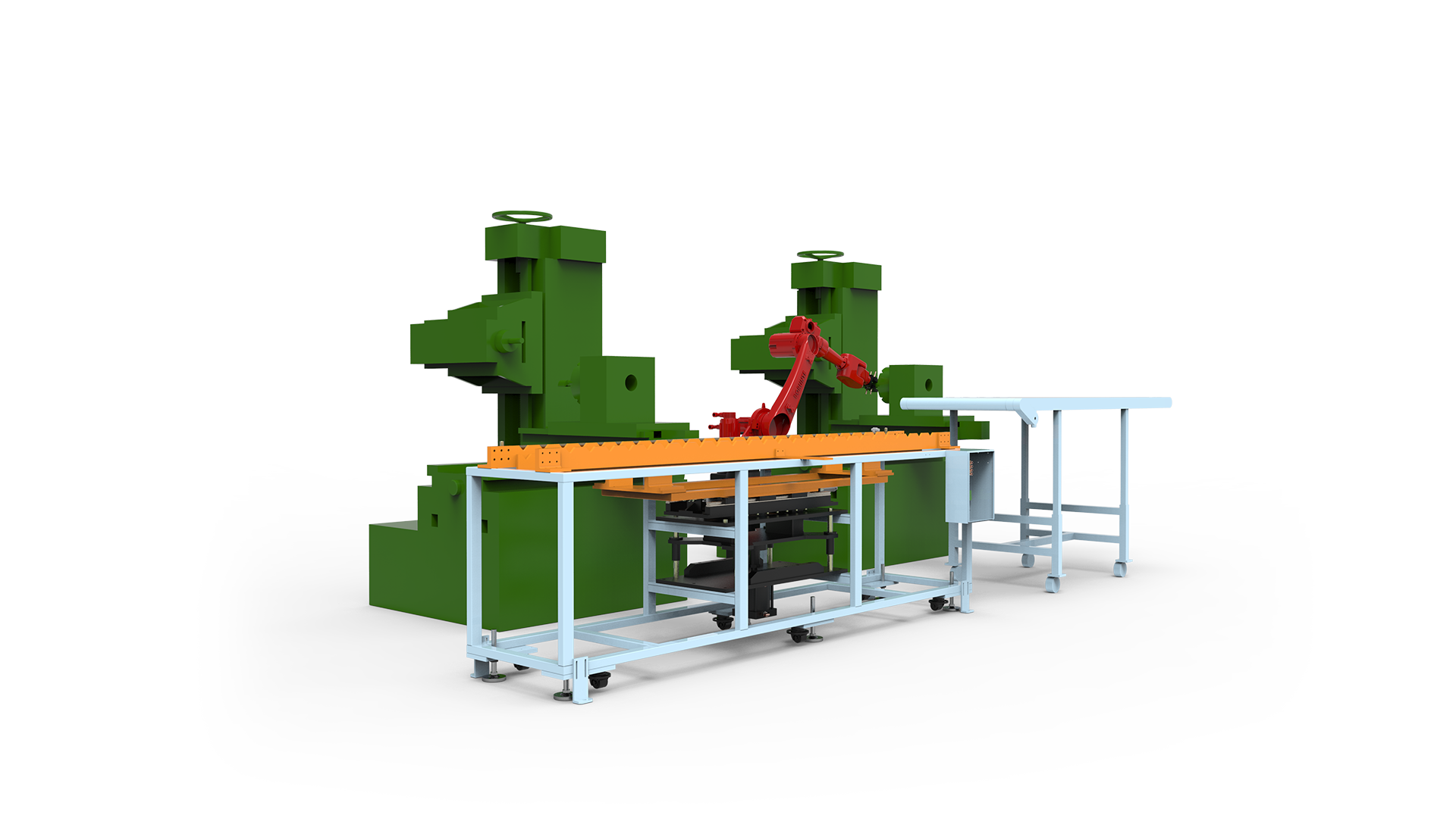
Specification snapshot: BRTIRUS1820A
| Parameter | Value |
|---|---|
| Robot type | Six-axis industrial robot |
| Arm reach | 1,895 mm |
| Rated payload | 20 kg |
| Repeatability | ±0.05 mm |
| Robot weight | Approx. 230 kg |
| Power capacity | 5.87 kVA |
| CE conformity | Yes — certificate DPWD/03/0646/2025 (2006/42/EC Machinery, 2014/35/EU Low Voltage, ICG) |
| Explosion-proof variant | Not available for this model |
| Declared applications | Handling, loading/unloading, palletizing, spraying, welding |
Applications beyond the declared list — such as deburring, grinding, polishing, gluing, vision sorting, laser cutting, or assembly — are not confirmed for this model and should be discussed with YGT engineers against the specific process.
FAQ
Q: What is the working reach of the BRTIRUS1820A, and how much of it is usable in a feeding cell? A: The published arm reach is 1,895 mm. In a feeding cell, the usable reach at the pick and place points is reduced by the gripper offset from the wrist flange, the bar overhang beyond the grip point, and the lift height needed to clear the layer below. The practical check is to plot both points plus the lift clearance inside the envelope with margin, measured from the wrist flange rather than the robot base.
Q: How do I check gripper swing clearance for long bars? A: Model the bar as a rigid body through the full transfer path, not just at the pick and place points. Check three clearances separately: the gripper body envelope as the wrist rotates, the arc traced by the bar ends, and the retract path out of the magazine. For long bars, the bar-end sweep is usually the governing constraint.
Q: The robot is rated at 20 kg — is that the maximum bar weight I can handle? A: The 20 kg figure is the rated payload at the flange. The bar weight has to be combined with the gripper assembly, the mounting offset, and the dynamic loads from acceleration. Because a long gripper holding a bar creates a significant moment arm, the moment load and the acceleration profile should be reviewed against the robot's load curves when the combined mass approaches the rated value.
Q: What feed table layout gives the shortest cycle time? A: A pre-indexing magazine that moves the next bar into the pick zone while the robot is transferring the current one hides the indexing time and reduces robot idle time. A single-station magazine that indexes only after the robot returns exposes the indexing time in every cycle, but is simpler and better suited to high-mix, low-volume production.
Q: Can the BRTIRUS1820A be used in an explosive atmosphere? A: No. This model does not have an explosion-proof variant. If the feeding application involves a hazardous atmosphere, that requirement needs to be addressed separately in the cell design.
Q: What applications are confirmed for this model? A: Handling, loading/unloading, palletizing, spraying, and welding are declared applications. Other processes — including deburring, grinding, polishing, gluing, vision sorting, laser cutting, and assembly — are not confirmed for this model and should be reviewed with YGT engineers against the specific process requirements.
Q: What is the CE status of the robot? A: The BRTIRUS1820A carries CE conformity under certificate DPWD/03/0646/2025, covering the 2006/42/EC Machinery Directive and the 2014/35/EU Low Voltage Directive, verified by ICG.
Next step
If you are specifying a bar or rod feeding cell, the most useful starting point is a layout sketch: the magazine position, the presentation point, the bar dimensions and weight range, and the required cycle time. Send that to YGT engineers and we can review the reach, swing clearance, and payload budget against the BRTIRUS1820A and advise on the cell layout — including whether a pre-indexing magazine is worth the additional mechanical complexity for your batch pattern.