Buyer's FAQ: Integrating YGT Welding Positioners with a BRTIRWD1506A Robot Welding Cell

Why buyers ask about positioners, not just robots
When a fabrication team moves from manual welding to a robot welding cell, the robot is usually the first thing on the purchase order — and the positioner is the first thing that causes trouble. A six-axis robot such as the BRTIRWD1506A has a 6 kg payload and a 1647 mm arm reach, which is more than enough for most light-to-medium fabricated parts. But a robot welds in one place. The positioner is what turns a single welding station into a production system: it presents the part at the right angle, rotates the workpiece so the weld stays in a comfortable position, and lets the operator load the next part while the robot is still welding the current one.
This FAQ collects the questions that manufacturing engineers, cell integrators, and procurement teams most often raise when they evaluate a YGT single-axis or double-axis welding positioner alongside a BRTIRWD1506A robot. The answers are written from an integration perspective — because that is where most of the risk, and most of the cost, actually sits.
The five questions that decide whether the cell works
1. Which side should the operator load and unload from?
The load/unload side is not a cosmetic decision. It determines cycle time, operator walking distance, fume extraction layout, and whether the safety enclosure can be kept compact.
For a single-axis positioner, the common arrangements are:
- Front-loading, robot behind: the operator faces the positioner and the robot welds from the far side. Compact footprint, but the operator is close to the arc and needs a physical guard or light curtain.
- Side-loading (90°): the operator stands to one side of the rotation axis. This is often preferred when parts are long or when a second fixture station is added, because the operator never crosses the robot's working envelope.
- Two-station (180° opposed): two fixtures on opposite ends of a rotating beam. The robot welds station A while the operator loads station B. This is the standard layout for volume production and is the arrangement most buyers mean when they say "double-axis positioner."
For a double-axis (tilting + rotating) positioner, the load side is usually set opposite the tilt direction so that gravity assists clamping rather than fighting it. In practice, the decision is driven by part geometry and by which side of the cell has room for a load buffer, a fixture cart, or a conveyor.
Rule of thumb: if the part weighs more than about 15–20 kg, or if load time exceeds roughly 30% of the weld time, a two-station arrangement usually pays for itself. Below that, a single-station positioner with a well-designed fixture is often the more economical choice.
2. How does rotation timing interact with the robot program?
Rotation timing is the single most common source of integration friction. The positioner and the robot are two independent motion systems, and they must agree on three things: when the positioner may rotate, how fast, and what the robot does while it rotates.
The usual integration patterns are:
| Pattern | How it works | Best for | Watch out for |
|---|---|---|---|
| Interlocked (stop-and-weld) | Robot finishes weld, moves to a safe home position, signals the positioner, positioner rotates, robot resumes | Most single-station cells; simple programming | Adds non-weld time to every cycle; home position must be outside the rotation envelope |
| Overlap (weld-while-rotate) | Positioner rotates slowly during welding so the torch stays in position | Long circumferential welds on pipe or rings | Requires coordinated motion or a positioner with a controlled, constant-speed axis; not all positioners are built for this |
| Two-station shuttle | Robot welds station A while station B is loaded; rotation happens only when both are ready | Volume production with manual loading | Rotation must be fully interlocked with the operator's side of the cell |
In a BRTIRWD1506A cell, the robot's controller and the positioner's controller normally exchange simple discrete signals (rotate command, in-position, fault) rather than full coordinated motion. That keeps the integration straightforward, but it means the robot program must include an explicit safe-park step before every rotation. Buyers should confirm with the integrator whether the positioner is expected to run in indexing mode (rotate to a fixed angle and stop) or continuous mode (constant rotation during welding) — the two require different hardware and different programming.
3. Grounding: why it matters more than most buyers expect
Welding current does not care where it returns. If the return path is not deliberately controlled, it will travel through the robot arm, the positioner bearings, the fixture, or the safety fence — and the result is erratic arcs, damaged bearings, and a robot that fails its insulation checks.
A properly grounded positioner setup has three separate concerns:
- Work return (welding ground): a dedicated ground clamp or brush block on the workpiece or fixture, sized for the welding current, with a clean contact surface. The return cable should run directly back to the welding power source, not through the machine frame.
- Positioner frame grounding: the positioner base and any rotating structure should be bonded to the cell's protective earth. This is a safety ground, not a welding return.
- Robot isolation: the robot should not be part of the welding current path. Insulating the fixture from the positioner frame, or using an insulated fixture plate, is a common way to keep weld current out of the robot's structure.
A practical check: with the welding source off, measure resistance from the fixture to the positioner frame and from the positioner frame to the building earth. If the fixture is intentionally insulated, that resistance should be high; if it is intentionally bonded, it should be low and stable. Either way, the reading should be documented and re-checked after fixture changes.
4. Fixture changeover: how long, and how often?
Fixture changeover is where high-mix production cells lose their advantage. The question buyers should ask is not "how fast can we change a fixture" but "how many changeovers per shift, and what does each one cost in lost arc time."
Common approaches, from simplest to most flexible:
- Bolt-on fixtures with dowel location: lowest cost, repeatable to a few tenths of a millimetre, but changeover is manual and typically measured in tens of minutes.
- Quick-change plates (zero-point or pin-locating): changeover drops to a few minutes and repeatability is maintained by the coupling itself. Higher fixture cost, but usually justified when changeovers exceed a few per shift.
- Pallet or cart systems: fixtures stay mounted on pallets that roll in and out of the cell. Changeover happens outside the cell, so the robot keeps welding. This is the most productive option for two-station positioners, but it needs floor space and a load/unload lane.
- Robot-tended fixture storage: in larger cells, the robot itself can pick fixtures from a rack. Rarely justified for a single 6 kg-payload robot cell, but worth knowing the option exists.
For a BRTIRWD1506A cell, the payload budget matters: the 6 kg payload must cover the torch, the torch mount, any collision sensor, and the fixture only if the robot is handling it. In most positioner cells the robot handles only the torch, so the fixture weight is carried by the positioner — but the positioner's own rated capacity should be checked against the fixture plus workpiece weight, not just the workpiece.
5. Safety envelope: what has to be inside the fence?
The safety envelope is the space the robot can reach, plus the space the positioner sweeps, plus the space the operator needs to load and unload. Getting this wrong is expensive in both directions: too small and the cell cannot be guarded properly; too large and the footprint cost is hard to justify.
Key points for a positioner-based welding cell:
- Robot reach plus tooling: the BRTIRWD1506A's 1647 mm reach is measured to the wrist flange. Add the torch length, the torch angle, and any collision sensor — the effective reach to the arc is longer.
- Positioner sweep: a tilting axis sweeps a volume, not a line. The swept envelope must be calculated at the maximum tilt angle, including the fixture and workpiece.
- Operator zone: the load/unload side must be separated from the robot and positioner envelope by a physical guard, a light curtain, or an interlocked door. A two-station positioner does not remove this requirement — it moves the boundary.
- Rotation interlock: the positioner must not rotate while the operator is inside the load zone. This is normally enforced by the positioner controller, the safety relay, and the cell's guard interlock together, not by software alone.
- Fume extraction: welding fume should be captured at the arc, not at the cell ceiling. This affects hood placement and sometimes the positioner's rotation direction.
A useful discipline is to draw the envelope in plan and elevation at the maximum tilt and rotation positions, then add the operator's standing and reach zones, then check that every boundary is either guarded or interlocked. If a boundary is neither, it is a finding.
What this means for the buying decision
A robot welding cell is a system, and the positioner is where the system meets the operator. The questions above are not technical trivia — they are the difference between a cell that runs at its designed cycle time and one that is constantly being adjusted.
When evaluating a YGT single-axis or double-axis positioner with a BRTIRWD1506A robot, the practical checklist is:
- Confirm the load/unload side against part geometry and floor layout.
- Decide indexing vs. continuous rotation, and confirm the positioner hardware matches.
- Specify grounding as a design requirement, not an afterthought.
- Estimate changeovers per shift and choose the fixture system accordingly.
- Draw the safety envelope at maximum tilt and rotation before approving the layout.
YGT's role in these projects is integration and application engineering: selecting the robot platform, designing the positioner and fixture arrangement, defining the signal interface between the robot and positioner controllers, and supporting commissioning on site. The robot model facts — payload, reach, repeatability — come from the manufacturer's published selection data; the cell design is where the integration work happens.
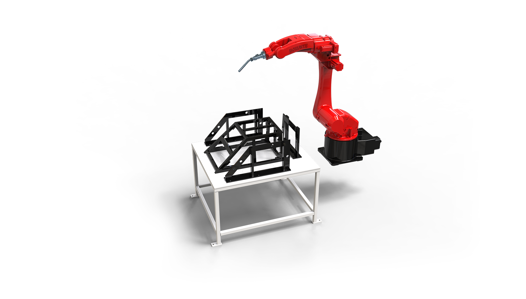
BRTIRWD1506A six-axis robot in a welding application on an industrial cart frame — a representative YGT project configuration.
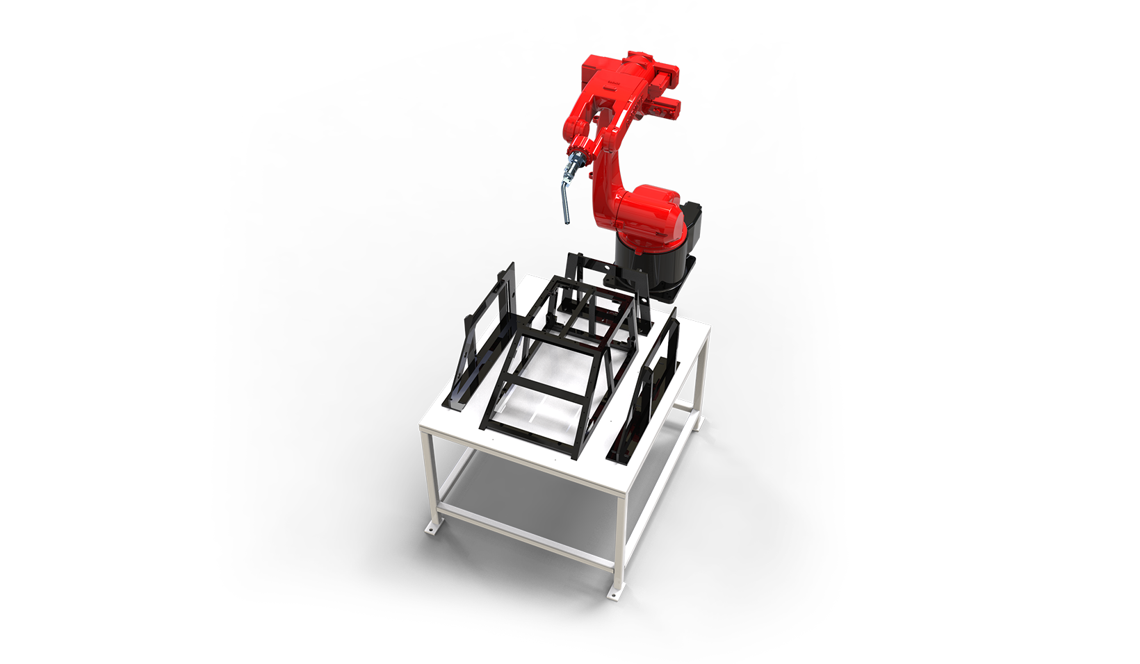
Positioner-based welding cell: the load/unload side, rotation envelope, and robot working area must be planned together.
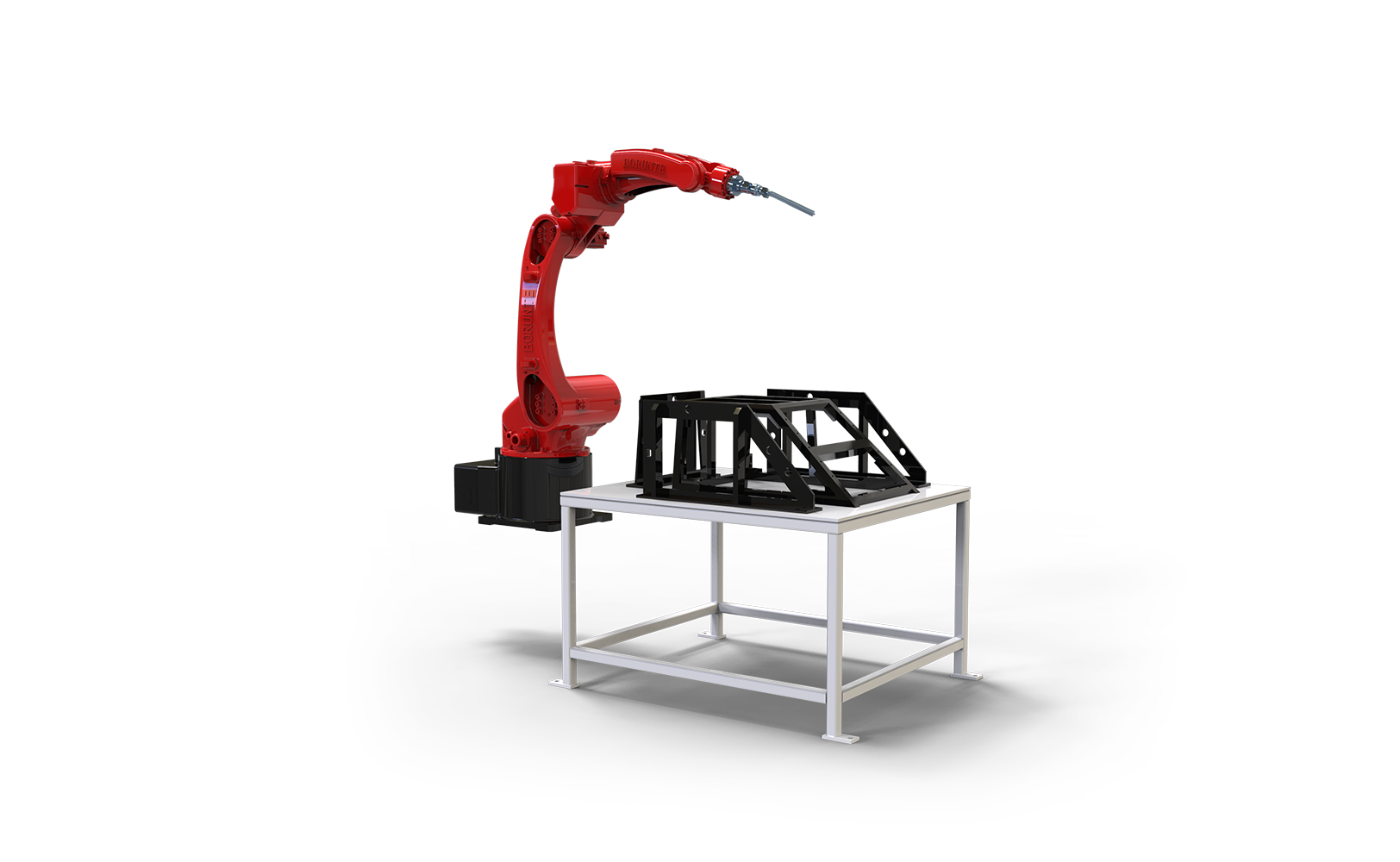
The safety envelope is defined by the robot reach, the positioner sweep, and the operator zone — all three, not just the robot.
Related equipment
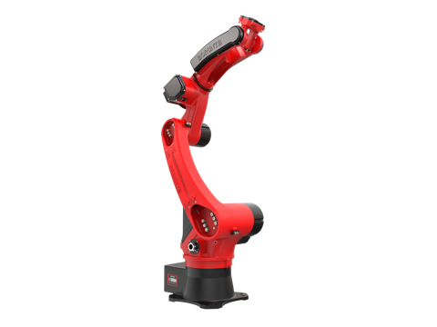
- BRTIRWD1506A six-axis welding robot — 6 kg payload, 1647 mm reach, ±0.05 mm repeatability, CE certified.
Next step
If you are planning a positioner-based welding cell, the most useful first conversation is about your part family, your changeover frequency, and your floor layout — not about the robot model. Those three inputs determine the positioner configuration, the fixture strategy, and the safety envelope, and they are the same three inputs that determine whether the cell meets its cycle time.
Send us a sketch of your part and your current load/unload flow, and our engineering team will come back with a proposed cell layout and the integration points that need to be confirmed.