Die Casting Extraction Cell Sourcing FAQ: Track-Mounted Six-Axis Robot in a One-to-Two Layout


Why one robot for two die casting machines
A die casting cell is not defined by the robot. It is defined by the mold open window — the short interval between the mold opening far enough for extraction and the point where the press must close again. Everything else in the cell, including how many machines one robot can serve, is a consequence of that window.
The one-to-two layout — a single six-axis robot mounted on a floor track, shuttling between two die casting machines — is one of the most common ways to raise robot utilization in a die casting shop. Instead of one robot idling beside one press, the robot moves along the rail and serves whichever machine has an open window. The trade-off is not the robot. It is the rail, the spacing, and the cycle logic.
This article answers the sourcing questions that come up most often when engineers and integrators specify this cell type, and clarifies how it differs from the wheel-loading and bar-feeding cell already covered elsewhere.
The customer problem: why the one-to-two layout is hard to specify
When a plant moves from manual extraction to automated extraction, the first design instinct is usually to place one robot at each press. That works, but it often leaves the robot idle for a large share of the cycle. The alternative — one robot on a track serving two presses — raises utilization but introduces a set of questions that do not exist in a single-press cell:
- How far apart can the two machines be before the rail becomes impractical?
- How long does the rail need to be, and how is that length actually calculated?
- Can the gripper reach into the die without the rail interfering with the press structure?
- How do the two machines' cycles interleave, and what happens when they drift?
- What is the failure mode if one press opens early or the other opens late?
These are not robot-selection questions in the narrow sense. They are cell-layout and cycle-coordination questions. Getting them wrong does not show up in the robot datasheet — it shows up as intermittent mold interference, missed extraction windows, or a rail that is 400 mm too short.
Why automate die casting extraction at all
Before the layout questions, it is worth restating what automation is actually buying in a die casting cell. It is rarely just labor substitution.
- Repeatable extraction timing. A robot enters and exits the mold on the same trajectory, at the same moment, every cycle. Human extraction timing varies with shift, fatigue, and attention.
- Consistent part handling. The same grip force and the same release point reduce the risk of part deformation and surface damage after ejection.
- Stable cycle time. Extraction becomes a fixed segment of the cycle rather than a variable one, which makes downstream scheduling more predictable.
- Reduced exposure to the mold area. Operators are removed from the immediate vicinity of the open mold and the hot part.
- Flexibility across part families. A programmable robot can be re-taught for a different part without mechanical rework of the cell.
None of these require a specific robot brand or model. They require a cell design that respects the mold window.
Solution logic: how a one-to-two extraction cell is actually built
The integration work in this cell type sits in four areas.
1. Track and travel. The robot is mounted on a linear rail (a floor track) that runs parallel to the two presses. The rail length is not simply the distance between the two machines — it must also account for the robot's approach position at each press, the safe parking position between cycles, and the cable-management envelope. Rail rigidity matters as much as rail length: a long rail that deflects under acceleration will degrade positioning at the die.
2. Gripper and reach into the die. The gripper must reach the part at the ejection position inside the open mold, grip it, and withdraw along a path that clears the mold halves and the press structure. This is where arm reach, wrist orientation, and gripper geometry interact. A gripper that works at press A may not clear the tie bars at press B if the two presses differ.
3. Cycle interleaving. The robot's schedule is a sequence of windows. If press A opens at t=0 and press B opens at t=Δ, the robot must complete extraction at A, travel, and be positioned at B before B's window closes. The design question is what Δ range the cell can tolerate before the schedule breaks.
4. Safety and mold protection. The cell must not enter a mold that is not fully open, and must not remain inside a mold that is about to close. This is enforced through press signals (mold-open confirmation, ejector status) and through the robot program's own entry/exit logic.
YGT Robot's role in this cell type is the integration layer: selecting the robot platform for the application, designing the track and gripper interface, coordinating the robot program with the press signals, and commissioning the cell on site. The robot itself is a BORUNTE platform selected for the application.
Key selection factors for a one-to-two extraction cell
Machine spacing and rail length
The spacing between the two die casting machines is the starting constraint. In practice, the rail length is driven by:
- the distance between the two extraction positions,
- the robot's approach and retreat distance at each press,
- a parking position that keeps the robot clear of both presses during their closed phase,
- cable and energy-chain routing along the rail.
A rail that only spans the two extraction points will usually be too short once parking and approach are included.
Gripper reach into the die
Reach into the die is a function of arm reach, the mounting height of the robot on the track, and the gripper length. Increasing gripper length to reach deeper into the mold increases the moment on the wrist and reduces the effective payload margin. This is one of the reasons payload and reach must be evaluated together rather than independently.
Payload margin
The part weight is only part of the payload. The gripper, any vacuum or pneumatic lines, and the dynamic loads during acceleration all count. A cell designed at the payload limit will have no margin for a heavier part or a more complex gripper later.
Repeatability at the die
Repeatability affects how reliably the gripper engages the part at the ejection position, especially when the part is not perfectly located. Tighter repeatability gives more tolerance in the gripper design.
Cycle interleaving tolerance
The cell should be designed around a realistic Δ between the two presses, not the ideal Δ. If the presses are mechanically coupled or share a cycle controller, Δ is stable. If they run independently, Δ drifts, and the cell needs either a scheduling strategy or a buffer position.
Controller and signal compatibility
The robot controller must exchange signals with both presses — mold open, ejector forward, ejector retracted, safe to enter, extraction complete. The specific signal interface depends on the press controller. This is confirmed per project during integration.
Comparison: BRTIRUS1820A vs BRTIRUS2030A vs BRTIRUS2110A
The three BORUNTE six-axis models commonly considered for this cell type differ mainly in payload, reach, and repeatability. The table below lists confirmed catalog parameters.
| Parameter | BRTIRUS1820A | BRTIRUS2030A | BRTIRUS2110A |
|---|---|---|---|
| Type | Six-axis robot | Six-axis robot | Six-axis robot |
| Payload | 20 kg | 30 kg | 10 kg |
| Arm reach | 1895 mm | 2068 mm | 2131 mm |
| Repeatability | ±0.05 mm | ±0.08 mm | ±0.05 mm |
| Weight | approx. 230 kg | approx. 310 kg | approx. 230 kg |
| Power capacity | 5.87 kVA | 6.11 kVA | 6.48 kVA |
| CE conformity | Yes | Yes | Yes |
| Explosion-proof variant | No | No | No |
A few practical notes on reading this table:
- BRTIRUS2110A has the longest reach but the lowest payload. It suits lighter parts where reach into a deep or offset mold is the binding constraint.
- BRTIRUS2030A has the highest payload but the widest repeatability of the three. It suits heavier parts where payload margin matters more than sub-0.1 mm positioning.
- BRTIRUS1820A sits between them, with 20 kg payload and ±0.05 mm repeatability, and is the model used in the one-to-two floor-track extraction project referenced below.
None of these models is explosion-proof. The BORUNTE range includes a single explosion-proof model, BRTIRSE2013F, which is outside the scope of this cell type.
A note on cycle interleaving
Interleaving two presses on one robot is a scheduling problem, not a robot problem. The cell designer's job is to define the Δ range the cell can absorb and to decide what happens outside that range — a wait state, a priority rule, or an alarm. This decision should be made explicitly during design, not discovered during commissioning.
How this cell differs from the wheel-loading and bar-feeding cell
A wheel-loading and bar-feeding cell and a die casting extraction cell can look similar on a plant floor — both involve a robot, a track, and a machine tool — but the constraints are different.
| Aspect | Wheel-loading / bar-feeding cell | Die casting extraction cell |
|---|---|---|
| Primary constraint | Part presentation and loading position | Mold open window and extraction timing |
| Robot entry condition | Machine ready for load | Mold fully open, ejector forward |
| Timing sensitivity | Moderate — loading window is relatively wide | High — extraction window is short and safety-critical |
| Failure mode | Misload, re-grip, line stop | Mold interference, missed extraction |
| Rail function | Move between load positions | Move between extraction positions and parking |
| Process coupling | Fixture and part geometry | Press signals, ejector timing, mold protection |
The key difference is what the robot is waiting for. In a loading cell, the robot waits for a fixture or a conveyor to present a part. In an extraction cell, the robot waits for a mold to open — and the window it must work within is defined by the press, not by the robot.
If you are sourcing both cell types, the extraction cell should be specified first, because its timing constraints are tighter and will constrain the layout of the surrounding equipment.
YGT experience
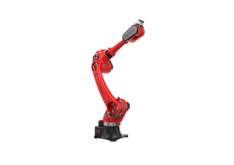
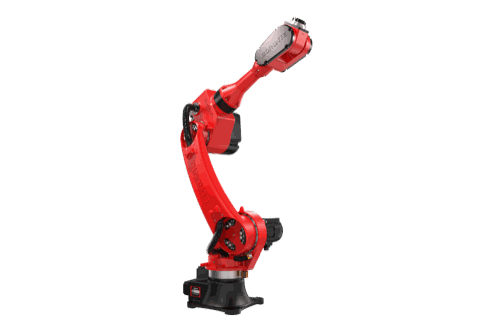
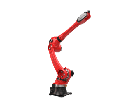
YGT Robot has delivered a one-to-two die casting extraction cell using a BRTIRUS1820A six-axis robot mounted on a floor track, serving two die casting machines. The project scope covered the track design, the gripper interface, the coordination of the robot program with the two presses' signals, and on-site commissioning.
The images below are from that project.


What this project illustrates is not a specific model choice. It is the layout logic: a single robot on a rail can serve two presses when the rail length, the gripper reach, and the cycle schedule are designed together. The same logic applies whether the presses are identical or not.
FAQ
Q: How do I decide the rail length for a one-to-two extraction cell?
Start from the two extraction positions, then add the robot's approach and retreat distance at each press, a parking position clear of both presses, and the cable-management envelope. A rail that only spans the two extraction points is usually too short. The final length is confirmed during cell layout, not from a formula.
Q: Can one robot really keep up with two die casting machines?
It depends on the extraction window of each press and the Δ between them. If the two windows overlap and the robot cannot complete extraction at one press before the other's window closes, the cell needs a scheduling strategy or a different layout. This is evaluated per project based on the actual press cycles.
Q: What happens if one press opens early or late?
The cell must not enter a mold that is not fully open, and must not remain inside a mold that is about to close. The robot program should be interlocked with press signals — mold-open confirmation and ejector status — so that extraction only proceeds inside the safe window. Outside that window, the robot waits or alarms.
Q: How much payload margin should I leave for the gripper?
The part weight is only part of the payload. The gripper, pneumatic or vacuum lines, and dynamic loads during acceleration all count. Designing at the payload limit leaves no margin for a heavier part or a more complex gripper later. In practice, leave margin for the gripper weight and for future part changes.
Q: Do I need a different robot for each press if the two presses are different sizes?
Not necessarily. The robot is selected for the more demanding of the two extraction tasks — the one requiring more reach or more payload. The gripper may need to be different at each press if the part geometry or the ejection position differs. This is confirmed during integration.
Q: Are these robots explosion-proof?
No. The BRTIRUS1820A, BRTIRUS2030A, and BRTIRUS2110A are not explosion-proof models. The BORUNTE range includes one explosion-proof model, BRTIRSE2013F, which is a different platform. If your die casting environment requires explosion-proof equipment, this should be raised during specification.
Q: What signals does the robot need from the die casting machine?
At minimum, mold-open confirmation and ejector status, so the robot only enters the mold inside the safe window. The specific signal interface depends on the press controller and is confirmed per project during integration.
Q: Can the same cell handle different part families?
A programmable robot can be re-taught for a different part without mechanical rework of the cell, provided the gripper can handle the new part and the extraction path still clears the mold. Gripper changeover is often the limiting factor, not the robot.
Related products
- BRTIRUS1820A six-axis robot
- BRTIRUS2030A six-axis robot
- BRTIRUS2110A six-axis robot
Next step
If you are specifying a one-to-two die casting extraction cell, the useful starting point is not a robot model — it is a layout sketch with the two press positions, the mold open window for each press, and the part weight and geometry. From there, reach, payload, rail length, and cycle interleaving can be evaluated together.
Share your cell layout and press cycle information with the YGT Robot engineering team, and we will review the extraction window, rail configuration, and gripper reach for your application.
YGT Engineering Team — YGT Robot (Guangdong Yigaite Intelligent Technology Co., Ltd.)
Robot platform parameters referenced in this article are confirmed from BORUNTE selection documentation. YGT Robot provides integration, application design, and on-site commissioning for die casting extraction cells.