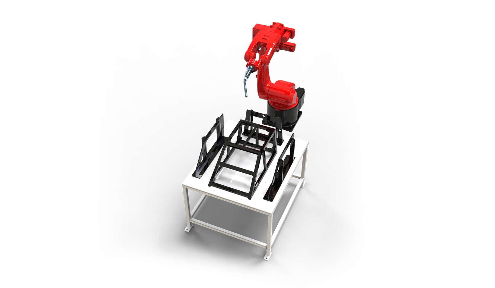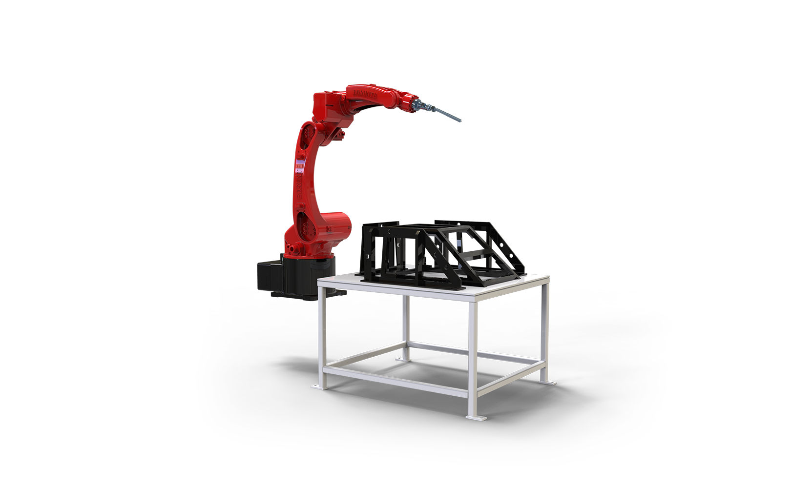
Sourcing a Dual-Axis Welding Positioner for a BRTIRWD1506A Robot Welding Cell: FAQ for High-Mix Fabrication Shops


A six-axis welding robot on its own is a motion device. What turns it into a production cell is the positioner underneath the fixture — and in high-mix fabrication shops, the positioner is usually where the money is won or lost. Two stations let the operator load one side while the robot welds the other, so the arc keeps burning instead of waiting for a clamp to close.
This FAQ collects the questions we see most often when shops and integrators specify a dual-axis positioner for a cell built around a 6 kg-class welding robot such as the BRTIRWD1506A. It is written for engineers, sourcing managers, and integrators who need to compare offers on something more useful than price per kilogram.
Why a positioner, and why two axes
Manual welding of a fabricated assembly often means repositioning the part several times so the joint stays in a comfortable position. That is fine when a person is holding the torch. It is not fine when the torch is on a robot arm: every reorientation either needs a re-fixture, a re-teach, or a robot pose that reaches the joint at a bad angle.
A positioner solves this by moving the work, not the torch. One axis tilts the part so gravity holds the puddle where you want it; the second axis rotates it so a long seam can be presented to the robot in segments. For a 6 kg payload robot with roughly 1.6 m of reach, the practical consequence is that the robot can stay in a narrow, well-behaved working envelope while the positioner does the large-scale motion.
Two stations add the second half of the value: the robot welds station A while the operator unloads and reloads station B. The cell's output is then set by whichever is slower — arc time or load time — and not by the sum of both.
Station changeover: what actually determines your arc-on ratio
Changeover is the single most under-specified item in positioner quotations. "Dual station" on a drawing can mean anything from a servo-indexed turntable to two fixtures on a manual swing arm.
Ask for these three numbers explicitly:
- Index time from station A to station B. Not the axis speed in degrees per second — the full commanded move including acceleration, settling, and the handshake with the robot. A slow index quietly caps your arc-on ratio no matter how fast the robot is.
- Load/unload time the design assumes. If the quotation assumes a 40-second load and your parts take 90 seconds, the second station is buying you less than you think.
- What happens during the index. Does the robot wait at a safe point, or can it continue welding on a third fixture? Does the welding source get an interlock-driven stop, or does the arc simply extinguish when the program pauses?
A useful sanity check: calculate the ratio of arc time to total cycle time for your actual part mix, once with a single station and once with two. If the second station does not move the number meaningfully for your shortest parts, the money may be better spent on fixture quick-change hardware.
Backlash and repeatability: separating robot accuracy from positioner accuracy
The BRTIRWD1506A is specified at ±0.05 mm repeatability. That figure describes the robot's ability to return to a taught point — it says nothing about where the positioner has put the workpiece.
This distinction matters because the two error sources combine differently depending on how you program:
- If you teach every weld point with the positioner at a fixed index position, positioner repeatability dominates the seam-to-seam variation, and the robot's accuracy mostly governs path fidelity within a single weld.
- If you program relative to a positioner-referenced frame and let the positioner index between segments of the same seam, backlash in the positioner's gear train shows up directly as seam offset at the joint between segments.
Practical sourcing questions on this point:
- What is the positioner's repeatability at the tooling mounting face, measured — not catalog-quoted — and at what radius?
- Is backlash measured at the output flange or at the motor? The two differ by the gear ratio, and only the first one matters to the weld.
- Does the positioner use a brake or a counterbalance to hold position when the servo is disabled? A tilt axis that drifts when power is removed is a safety and quality problem.
- For a horizontal rotary axis, what is the runout and axial float at the chuck or fixture plate?
A positioner with 0.05° of backlash at the output is not automatically better than one with 0.1° — what matters is whether the resulting linear error at the seam is inside your weld tolerance. Do that conversion before comparing offers.
Grounding path: the item that causes intermittent weld defects
Welding current has to return to the power source. If it returns through a positioner bearing, a servo shaft, or a robot axis, it will eventually damage them and it may cause arc instability long before that.
Sourcing points:
- Dedicated weld return path. The positioner should provide a specified grounding connection from the fixture plate back to the welding power source, with a cross-section adequate for the maximum welding current in your process — not a small bonding conductor intended for electrical safety.
- Insulated or isolated bearings. Where the design routes return current past a bearing, ask whether that bearing is isolated, and how the isolation is maintained after years of spatter and grinding dust.
- Grounding of the robot and positioner chassis is a separate requirement from the weld return path. Both are needed; neither substitutes for the other.
- Rotating grounds. A continuously rotating axis needs a slip ring or a flexible grounding strap rated for the current and duty cycle. Ask which one is used and what its service life is.
In a high-mix shop, the failure mode is easy to miss: the cell welds fine on one part family and shows sporadic porosity or arc wander on another, because the return path resistance changes with position. If you are troubleshooting that symptom after installation, the positioner ground path is one of the first things to check.
Cable management: torch, wire, gas, and the positioner's own dress package
A dual-station cell has two cable populations that are often specified by different people: the robot dress package (torch, wire feeder, gas, water, and the welding signal bundle) and the positioner's own servo and sensor cabling. They interact.
Questions worth asking at quotation stage:
- Torch dress routing relative to the positioner envelope. Does the robot dress have clearance to reach both stations without dragging on the positioner or the fixture? Ask for the reach study, not just the reach figure.
- Wire feed distance. A longer torch cable run increases push force and makes soft wires more prone to bird-nesting. If the wire feeder has to sit far from the torch, ask how the feed path is supported.
- Positioner cable carriers. Rotary and tilt axes need cable carriers or a rotary union rated for the number of cycles the cell will run. Ask for the bend radius and the cycle rating, and whether the carrier is accessible for replacement without dismantling the fixture.
- Service loops at the station interface. The point where the fixture's tooling cables cross from the fixed frame to the moving table is where most cable failures originate. A connector-based interface with a defined service loop is easier to maintain than a hard-wired bundle.
Safety interlock sequencing: where cells fail audits
The sequencing between the robot controller, the positioner, the welding power source, and the perimeter guarding is what determines whether the cell can be operated safely and whether it will pass a site audit.
A workable sequence for a two-station cell generally looks like this:
- The operator requests access to station B; the cell confirms the robot is not in station B's zone.
- The station B light curtain or interlocked gate permits entry only while station B is in the load position.
- Indexing from B to A is inhibited while station B's gate is open.
- On index completion, the positioner reports "in position" before the robot is released to weld.
- Emergency stop acts on the robot, the positioner drives, and the welding source together — not on the robot alone.
The details that get missed:
- Reset behaviour. After an interlock trip, does the cell require a manual reset at the operator station, or does it resume automatically? Automatic resume is a common audit finding.
- Positioner brake release on E-stop. The brake should engage, and the axis should not coast. Ask how the brake is wired relative to the drive enable.
- Welding source state. On an interlock stop, the arc should be extinguished by the welding source, not merely by the robot ceasing motion.
- Communication path. The positioner's drive and the robot controller need a deterministic handshake. If the positioner is on a fieldbus the robot does not natively speak, a gateway is the usual route — and the handshake timing through that gateway should be part of the acceptance test.
Comparing positioner options at a glance
The table below is a sourcing checklist rather than a product comparison. Fill it in for each offer you receive.
| Sourcing item | What to ask for | Why it matters in high-mix work |
|---|---|---|
| Station changeover | Full index time including settle and handshake | Caps arc-on ratio regardless of robot speed |
| Positioner repeatability | Measured value at tooling face, with radius stated | Determines seam-to-seam variation |
| Backlash | Value at output flange, not motor | Converts directly to seam offset on indexed seams |
| Brake / counterbalance | Type, and behaviour on power loss | Safety and position hold |
| Weld return path | Cross-section, connection point, isolation of bearings | Prevents intermittent arc instability and bearing damage |
| Rotary ground | Slip ring or strap, current rating, service life | Long-term return path integrity |
| Cable carriers | Bend radius, cycle rating, accessibility | Maintenance downtime |
| Interlock reset | Manual vs automatic, and where | Site audit compliance |
| E-stop scope | Robot + positioner + welding source | Personnel safety |
| Handshake path | Native fieldbus or gateway, with timing | Acceptance test predictability |
How YGT approaches positioner integration
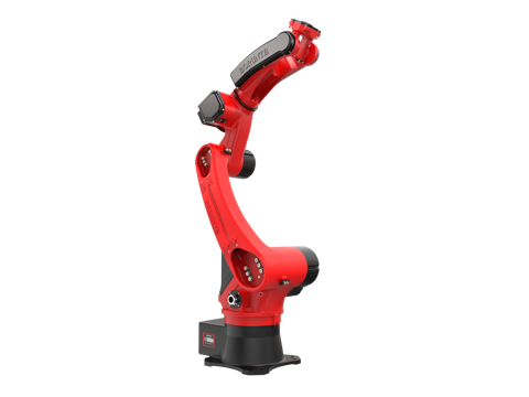
YGT Robot (Guangdong Yigaite Intelligent Technology Co., Ltd.) works as a system integrator: we take the application — the part family, the joint access requirements, the fixture concept, the cycle time target — and build the cell around a suitable robot platform and positioner. In our welding work, the robot platform is typically a BORUNTE model such as the BRTIRWD1506A, selected for its 6 kg payload, 1647 mm reach, and ±0.05 mm repeatability; the positioner, fixturing, grounding, cable management, and interlock architecture are engineered to the application.
That division matters when you are sourcing. The robot's published specifications are the robot's; the cell's behaviour — changeover time, seam consistency, grounding integrity, and safe sequencing — is the integrator's responsibility. When you evaluate an offer, ask which party owns each of those items.
On the control side, the BRTIRWD1506A supports CAN, Modbus RTU, Modbus TCP, and digital I/O natively. Fieldbuses such as EtherCAT, Profinet, CC-Link, and DeviceNet are not native to the controller but can be bridged through a gateway or protocol converter, with the specific arrangement confirmed against the PLC and drive selection for the project. If your plant standard is one of those, raise it early — it affects the handshake design and the acceptance test, not just the bill of materials.
FAQ
Does a dual-axis positioner need to be servo-driven, or is a manual index acceptable? It depends on your part mix and your arc-on target. A manual index is cheaper and simpler, but the changeover time is operator-dependent and the position is not verified by the controller. For a cell where the second station is meant to keep the arc burning, a servo-indexed positioner with a confirmed in-position signal is usually the more predictable choice.
Can the BRTIRWD1506A reach both stations without a rail? Reach depends on where the positioner is placed relative to the robot base and on the fixture height. The robot's arm reach is 1647 mm, but the usable working envelope at the torch, with the dress package fitted, is smaller. A reach study using your actual fixture geometry is the right way to answer this — not a comparison of the reach figure against the station spacing.
What repeatability should I specify for the positioner? Specify it as a linear tolerance at the seam, then work backwards to an angular value at your fixture radius. A positioner quoted at a given angular repeatability at a 500 mm radius produces roughly nine times the linear error it would at a 55 mm radius. The number only means something with the radius attached.
How do I know whether the grounding path is adequate? Ask for the specified weld return cross-section, the connection point on the fixture plate, and whether the positioner bearings are isolated from the return path. Then verify it at commissioning with a resistance measurement from the fixture plate to the power source return, at several axis positions.
Is a gateway acceptable for the positioner-to-robot handshake? It can be, provided the timing is verified. A gateway adds latency and a failure point; the acceptance test should include the handshake under the worst-case cycle, not just a static check that the signals map correctly.
What is the most common cause of a positioner failing a safety audit? Automatic reset after an interlock trip, and emergency stop circuits that act on the robot but not on the positioner drives or the welding source. Both are design decisions, and both are cheap to get right at the quotation stage.
Next step
If you are specifying a dual-station welding cell, the most useful thing you can send us is the part family, the joint access drawing, and your target cycle time. From those we can tell you which of the items above will actually constrain your cell — and which are not worth paying for in your application.