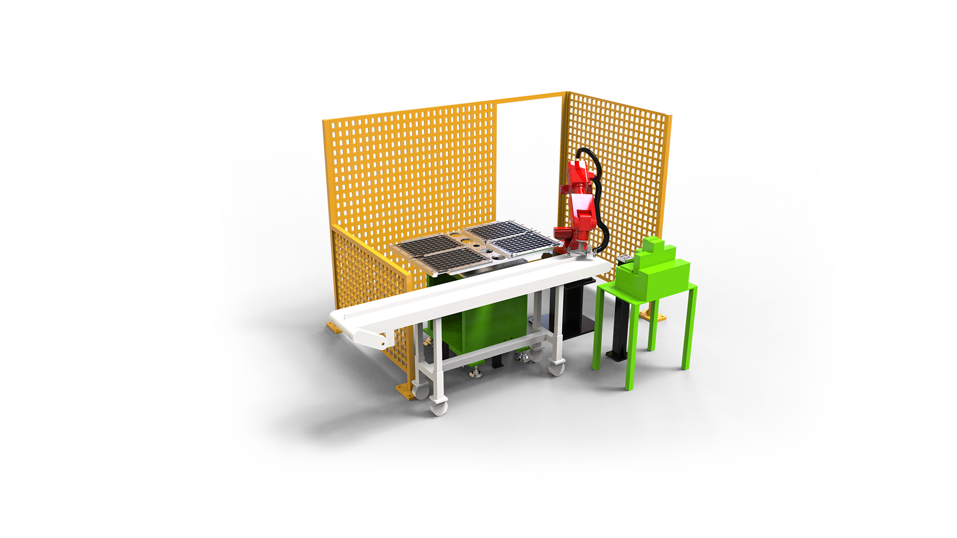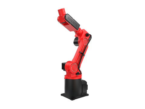
Specifying a BRTIRUS0805A Six-Axis Robot Cell for Semiconductor Chip Loading and Unloading: A Sourcing FAQ


Why chip handling is a specification problem, not a robot-shopping problem
In semiconductor back-end and test operations, the robot is rarely the hard part. The hard part is the interface between a micron-level placement requirement and everything around the robot: the tray stacker, the magazine elevator, the ESD path to ground, the cleanroom airflow, the tester handshake, and the takt time the line was designed around.
Sourcing engineers who evaluate a six-axis cell for chip loading and unloading tend to ask the same five questions. This guide works through them in the order they usually surface in a specification review, using the BRTIRUS0805A as the reference platform. Where a value is a published catalogue parameter, it is stated as such. Where a value depends on the gripper, the tray nest, or the tester interface, it is flagged as something to confirm during cell design rather than assumed.
The five sourcing questions that decide the cell
1. Is ±0.05 mm repeatability enough for chip placement?
The BRTIRUS0805A is a six-axis robot with a published repeatability of ±0.05 mm, a payload of 5 kg, and an arm reach of 990 mm. For chip loading and unloading into trays, tubes, and test sockets, that repeatability figure is usually adequate — but only if the specification treats it correctly.
Repeatability is not accuracy. Repeatability describes how tightly the robot returns to the same commanded point; accuracy describes how close that point is to the nominal CAD position. A cell that must place a part into a pocket with 0.2 mm clearance needs both, plus a vision or mechanical datum to absorb the difference between the robot frame and the tray frame. In practice, the placement budget is consumed by four contributors:
- robot repeatability (±0.05 mm published)
- gripper and tooling deflection under vacuum or clamp load
- tray nest positional tolerance and stacker repeatability
- thermal drift over a production shift
A useful rule during specification: allocate no more than one third of the total placement tolerance to the robot, and design the remaining budget into the tooling and the nest. If the pocket clearance is tighter than about 0.15 mm, plan for a vision fine-alignment step or a compliant nest rather than relying on the robot alone.
2. What does ESD-safe end-of-arm tooling actually require?
ESD is a system property, not a gripper accessory. An ESD-safe end-of-arm tool for chip handling typically needs:
- Dissipative or conductive contact surfaces at the pick point, so charge does not accumulate on the part
- A continuous ground path from the tooling through the robot wrist and the cell frame to the facility ground, measured and documented
- Non-outgassing, particle-shedding-controlled materials compatible with the cleanroom class
- No isolated conductors near the device — an ungrounded metal insert is worse than a plastic one
The robot arm itself is a grounded machine structure, but the ground path through a rotating wrist joint and a quick-change tool changer must be verified, not assumed. During FAT, specify a surface resistance check at the pick point and a charge-decay measurement with a representative device.
This is one of the areas where the cell integrator's work matters more than the robot datasheet. The tooling design, the grounding scheme, and the verification record are what a back-end engineer will be asked to sign off on.
3. Tray and magazine handling: what has to be specified?
Tray and magazine handling is where most chip handling cells succeed or fail in production. The robot moves the device; the tray stacker and magazine elevator determine whether the cell can run unattended.
Specify the following explicitly:
| Handling element | What to specify | Why it matters |
|---|---|---|
| Tray stacker | Stack capacity, tray pitch tolerance, elevator repeatability, empty/full sensing | Determines unattended run time and jam recovery |
| Magazine elevator | Slot pitch, magazine weight, load/unload side, interlock logic | Misalignment here causes the most common crash mode |
| Tray nest | Nest flatness, pocket datum, presence sensing per pocket | Directly consumes placement tolerance |
| Part presence | Vacuum or optical sensing at the pick point | Prevents double-pick and empty-pick faults |
| Reject path | Dedicated reject tray or bin with confirmation | Keeps suspect parts out of the good stream |
A 5 kg payload robot is comfortably within range for typical tray and magazine handling, but the payload figure includes the gripper, the vacuum generator if wrist-mounted, and the part. Budget the tooling mass first, then confirm the remaining payload against the heaviest device-plus-tray combination the cell will see.
4. Is the cell cleanroom compatible?
The BRTIRUS0805A carries CE conformity (machinery directive 2006/42/EC and low-voltage directive 2014/35/EU) and is not an explosion-proof model — the explosion-proof variant in this robot family is a separate model. Neither of those facts answers the cleanroom question directly.
Cleanroom compatibility for a robot cell is an assembly-level property. It depends on:
- the robot's surface finish and the feasibility of wiping it down
- the lubrication scheme and whether the wrist joints are sealed against particle emission
- the vacuum exhaust path — unfiltered exhaust is a common and avoidable particle source
- cable routing and the number of horizontal surfaces that collect particles
- the airflow interaction between the robot envelope and the laminar downflow
For a Class 1000 or Class 10000 back-end environment, a standard six-axis robot with a sealed wrist, filtered vacuum exhaust, and cleanroom-compatible cable management is often workable. For tighter classes, the specification should include a particle-emission test in the actual enclosure rather than a datasheet claim. Confirm the target class with the cell designer early, because it changes the tooling and the exhaust design, not just the robot.
5. How do you match cycle time to the tester or the line?
Cycle time in a chip handling cell is rarely limited by the robot's free-air speed. It is limited by the slowest of:
- the pick-and-place transfer time, including vacuum establish and vacuum break
- the tester or handler handshake and socket actuation
- the tray index time
- the vision alignment step, if one is used
A practical approach during sourcing is to build a cycle-time model with four line items — transfer, tooling actuation, station handshake, and index — and then measure a representative cycle at FAT with the actual device and the actual tray. Published robot speed figures are useful for sizing the transfer component and little else.
If the line takt is fixed, the usual levers are tooling actuation time (vacuum generator sizing, venturi versus pump), dual-lane tray indexing, and overlapping the robot transfer with the tester handshake. These are cell design decisions, and they should be on the table before the robot model is locked.
Comparing the BRTIRUS0805A specification against chip handling requirements
| Parameter | BRTIRUS0805A published value | Relevance to chip loading/unloading |
|---|---|---|
| Configuration | Six-axis robot | Wrist orientation flexibility for tray and socket access |
| Payload | 5 kg | Tooling plus device plus tray margin |
| Arm reach | 990 mm | Cell footprint and tray/magazine layout |
| Repeatability | ±0.05 mm | Placement budget contributor, not the whole budget |
| Weight | Approx. 53 kg | Floor or frame mounting and cleanroom ceiling load |
| Power capacity | 3.67 kVA | Facility and panel sizing |
| CE conformity | Yes (2006/42/EC, 2014/35/EU) | European market entry requirement |
| Explosion-proof | Not available on this model | Not required in typical back-end areas; confirm if solvent exposure exists |
| Confirmed applications | Handling, loading/unloading, palletizing, spraying, welding | Chip handling falls under handling and loading/unloading |
Two notes on reading this table. First, the confirmed application list is the enterprise-declared scope; applications outside it — including some assembly and inspection tasks — are not covered by that declaration and should be discussed with the engineering team rather than assumed. Second, the CE conformity is a robot-level conformity, not a certification of the finished cell; the cell integrator is responsible for the cell-level declaration.
Where integration decisions outweigh the robot model
The BRTIRUS0805A is a BORUNTE robot platform. YGT Robot's role is the integration and application work around it: gripper and end-of-arm tooling design, tray and magazine interface, ESD grounding scheme, tester handshake, cleanroom enclosure, and the commissioning and service that follows.
That division matters during sourcing because the five questions above are mostly answered by the cell design, not by the robot catalogue. A cell built around a robot with adequate repeatability and payload can still fail on tray nest tolerance or an unverified ground path. Conversely, a well-designed cell can absorb a robot that is not the tightest in its class.
For sourcing engineers, the practical implication is to ask the integrator for the cell-level specification, not just the robot datasheet: the placement budget breakdown, the ESD verification method, the tray and magazine tolerances, the cleanroom class and the particle test method, and the cycle-time model with measured FAT data.
FAQ
Is ±0.05 mm repeatability sufficient for placing chips into test sockets? It can be, depending on socket clearance and whether a vision or compliant alignment step is used. Repeatability is only one contributor to the placement budget; tooling deflection, nest tolerance, and thermal drift also consume it. Specify the full budget rather than the robot figure alone.
Does the BRTIRUS0805A support ESD-safe operation out of the box? The robot is a grounded machine structure, but ESD safety at the device depends on the end-of-arm tooling, the ground path through the wrist and tool changer, and the materials used. These are cell design items and should be verified with a surface resistance and charge-decay test at FAT.
Can the robot handle both trays and magazines in one cell? The 5 kg payload and 990 mm reach are generally sufficient for combined tray and magazine handling, but the tooling mass, the heaviest device-plus-tray combination, and the layout must be checked. Confirm the handling scope with the integrator during cell design.
Is this robot suitable for a cleanroom environment? Cleanroom compatibility is an assembly-level property. A standard six-axis robot with sealed wrist joints, filtered vacuum exhaust, and appropriate cable management can often meet Class 1000 or Class 10000 back-end requirements. For tighter classes, specify a particle-emission test in the actual enclosure.
Is the BRTIRUS0805A explosion-proof? No. In this robot family, explosion-proof construction is available only on a separate model. If the cell area has solvent exposure, confirm the hazardous-area classification before selecting the platform.
How should cycle time be validated before purchase? Build a cycle-time model covering transfer, tooling actuation, station handshake, and tray index, then measure a representative cycle at FAT with the actual device and tray. Published robot speed figures size the transfer component only.
Which applications are confirmed for this model? The confirmed application scope covers handling, loading/unloading, palletizing, spraying, and welding. Applications outside that scope should be discussed with the engineering team rather than assumed from the robot's general capability.
Who is responsible for the CE declaration of the finished cell? The BRTIRUS0805A carries robot-level CE conformity. The finished cell requires its own conformity assessment, which is the responsibility of the cell integrator.
Related product
- BRTIRUS0805A six-axis robot
Next step
If you are specifying a chip handling cell, the most useful first conversation is not about the robot model but about the placement budget, the tray and magazine interface, and the takt time. Send us the device dimensions, the tray or magazine specification, the target cleanroom class, and the line takt, and the engineering team can work through the cell-level questions with you before any hardware is selected.