How to Specify a Robot Cell for Glue Insertion and Insert Molding: An FAQ Guide for Injection Molding Engineers

YGT Engineering Team · YGT Robot (Guangdong Yigaite Intelligent Technology Co., Ltd.)
The problem: the mold is ready, but the cell is not
Most insert molding and glue insertion projects do not fail because of the mold. They fail because the cell around the mold was specified late, and specified loosely.
Typical symptoms on the shop floor:
- Insert placement is still manual, so cycle time drifts with operator fatigue and shift changes.
- The robot was chosen from a payload figure alone, without checking whether it can actually reach into the cavity at the right angle.
- Insert seating depth varies, and the variation only shows up as flash, short shots, or rejected parts after the mold is already cut.
- The cell works in the lab but not in production, because part presentation, glue dispensing, and mold-open timing were never treated as one system.
If you are an injection molding engineer or process planner writing a specification right now, the questions below are the ones worth answering before you commit to a robot model.
Why automate glue insertion and insert molding at all
The case for automation here is not “replace people.” It is repeatability in a process where small position errors become scrap.
- Consistent insert seating. A robot places the insert to the same depth and angle every cycle. Manual placement cannot hold that tolerance across a full shift.
- Repeatable glue bead placement. When dispensing is carried by the same motion path every cycle, bead position and volume stop being a variable.
- Stable cycle time. Mold-open windows are short. Predictable robot motion lets you plan the mold and the cell together instead of tuning around human pacing.
- Production flexibility. A programmed cell can run multiple part variants — a different insert, a different cavity layout — without retooling the whole station.
- Long-term cost structure. The economics usually come from yield and uptime, not from headcount alone.
Solution logic: the mold, the robot, and the interface are one system
A robot cell for insert molding is not a robot bolted next to a press. It is an integration problem with four coupled layers:
- Mold and part interface — cavity layout, insert orientation, ejection, and how the insert is presented to the robot (vibration bowl, tray, magazine, or hand-loaded nest).
- Robot selection — payload, reach, repeatability, and wrist orientation at the moment of insertion, not just at the pick position.
- End-of-arm tooling — gripper or vacuum design for the specific insert, plus glue dispensing hardware if the process requires it.
- Cell control and safety — sequencing with the molding machine, mold-open signal handshake, guarding, and operator access.
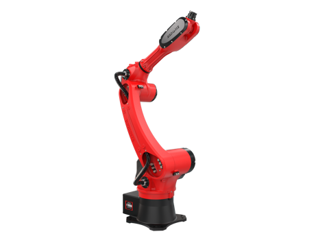
YGT Robot works as a system integrator and application solution provider in this space: we analyze the process, select a suitable robot platform, and integrate the robot, tooling, and control interface into a working cell. The robot platform itself is sourced from established manufacturers — for the reference project below, the platform is a BORUNTE BRTIRUS1510A six-axis robot.
Key selection factors
Payload: count the tooling, not just the part
The insert may weigh a few grams. The gripper, the dispensing nozzle, the mounting plate, and any cabling all add up. Size the payload against the total moving mass at the wrist, with margin for acceleration forces.
Reach: verify it at the insertion point, not the pick point
The number that matters is whether the robot can reach the deepest cavity position at a workable wrist angle. A robot that reaches the pick nest easily may still be cramped at the far cavity of a large mold.
Repeatability and accuracy
Insert seating and glue bead placement are position-critical. Repeatability should be checked against the tolerance your process actually needs — not against the tightest number available.
Wrist payload and orientation range
Insert molding often requires the tool to approach the cavity from a specific direction, sometimes in a confined space between platens. Wrist range of motion is frequently the real constraint, not arm reach.
Cycle time and mold-open window
The robot must complete pick, move, insert, and retreat inside the mold-open window. This is a sequencing calculation, and it should be done before the mold is finalized.
Part presentation method
Vibration bowl, tray, magazine, or manual nest — each has a different reliability profile and a different impact on cell footprint and operator involvement.
Glue dispensing integration
If the process includes glue insertion, the dispensing system, its control interface, and its motion path need to be specified together with the robot, not added afterward.
Controller and signal compatibility
The robot controller must exchange signals cleanly with the molding machine — mold open, mold closed, permission to enter, cycle complete. This is a per-project integration question, and it should be confirmed against the specific controller and machine combination.
Environment and certification
Check the cell environment (temperature, dust, any solvent exposure) and the certification requirements that apply in your market. The BRTIRUS1510A carries CE conformity (2006/42/EC machinery and 2014/35/EU low voltage). It is not an explosion-proof model; if your process area requires explosion protection, that must be addressed separately.
Quick comparison: manual vs. semi-automatic vs. robotic cell
| Factor | Manual insertion | Semi-automatic (fixture-assisted) | Robotic cell |
|---|---|---|---|
| Insert seating consistency | Operator-dependent, drifts across shift | Improved by fixture, still operator-loaded | Programmed position, repeatable cycle to cycle |
| Cycle time stability | Varies with pace and fatigue | More stable, limited by manual load | Determined by robot motion and mold window |
| Multi-variant changeover | Re-learn by hand | Fixture change | Program change |
| Glue bead placement | Manual, high variation | Fixture-guided, moderate variation | Path-controlled, repeatable |
| Operator role | Places inserts, runs cycle | Loads fixture, supervises | Supervises cell, handles exceptions |
| Best fit | Low volume, simple inserts | Mid volume, moderate tolerance | Higher volume, tight tolerance, multi-cavity |
Reference configuration: eight-cavity toothbrush overmolding
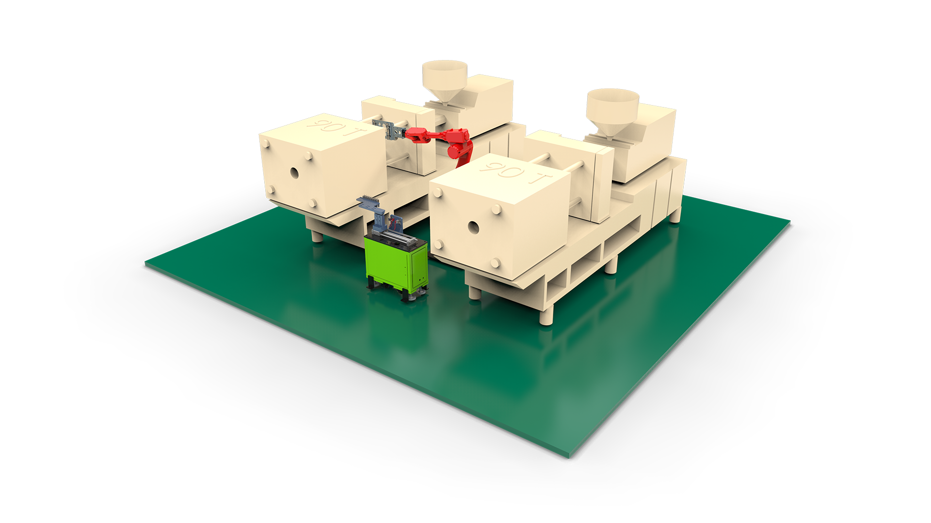
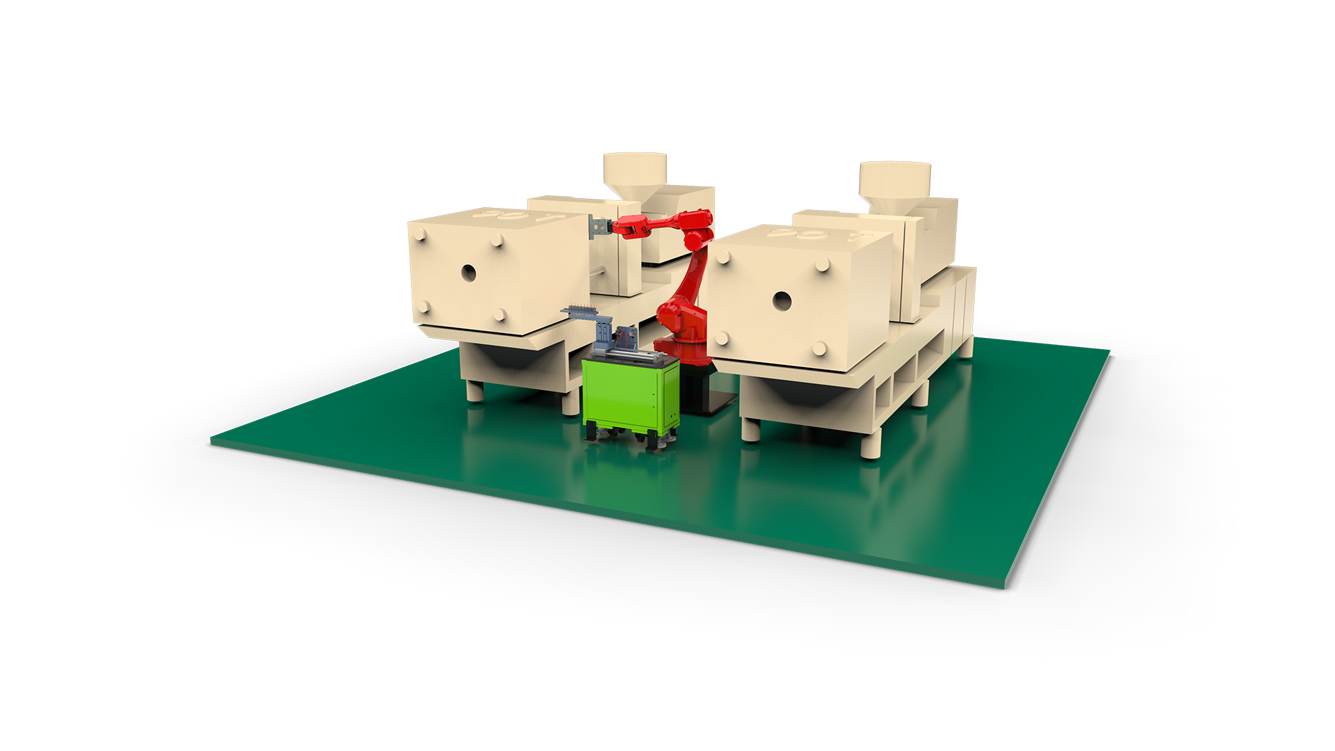
One configuration YGT Robot has worked with is an eight-cavity toothbrush insert overmolding cell built around a BRTIRUS1510A six-axis robot.
Key parameters of the platform used in this configuration:
| Parameter | Value |
|---|---|
| Robot type | Six-axis |
| Payload | 10 kg |
| Arm reach | 1587 mm |
| Repeatability | ±0.05 mm |
| Robot weight | 152 kg |
| Power capacity | 5.06 kVA |
| CE certification | Yes (2006/42/EC, 2014/35/EU) |
| Explosion-proof | No |
Why this platform fits this class of application: the 10 kg payload leaves room for a gripper and any dispensing hardware on top of a small insert; the 1587 mm reach covers a multi-cavity mold plus the part presentation area without moving the base; and the ±0.05 mm repeatability supports consistent insert seating across eight cavities.
YGT Robot's role in this configuration is the integration: process analysis, robot platform selection, end-of-arm tooling, sequencing with the molding machine, and on-site commissioning.
FAQ
Q: How do I calculate the payload I actually need? Add the insert weight, the gripper or vacuum tool, the mounting plate, any dispensing hardware, and cabling. Then add margin for dynamic acceleration — the effective load during a fast move is higher than the static weight. If the total is close to the rated payload, step up a size.
Q: The robot reaches the pick nest but not the far cavity. What do I check? Check reach at the insertion point and the wrist orientation needed to enter the cavity — not the reach at the pick position. In many insert molding cells the limiting factor is wrist range of motion between the platens, not arm length.
Q: Can the robot run inside the mold-open window? That depends on the mold-open time, the distance from the presentation nest to the cavity, and the number of inserts per cycle. It is a sequencing calculation, and it should be done with the mold timing in hand rather than assumed.
Q: How is glue dispensing integrated with the robot? The dispensing system is typically carried on or near the end-of-arm tooling, with its motion path programmed as part of the robot cycle. The dispensing controller and the robot controller need a clean signal interface. Because this varies by process and by equipment, it is best confirmed against your specific application.
Q: Does the BRTIRUS1510A support explosion-proof environments? No. The BRTIRUS1510A is not an explosion-proof model. If your process area requires explosion protection, that requirement needs to be handled separately.
Q: What certifications does the BRTIRUS1510A carry? It carries CE conformity under 2006/42/EC (machinery) and 2014/35/EU (low voltage).
Q: Can one cell handle more than one insert type or part variant? In most cases yes, through program changes and, where needed, tooling changes. The practical limit is how much changeover time your production plan can absorb.
Q: What should I prepare before requesting a cell quotation? Part drawings, insert drawings, mold layout and cavity count, molding machine model and controller, target cycle time, mold-open time, and any glue dispensing requirement. With those, the cell configuration can be specified rather than estimated.
Related products
Related cases
Next step
If you are specifying an insert molding or glue insertion cell, the useful conversation is about your mold layout, cycle time, and insert presentation — not about a robot model in isolation. Send us your part and mold data, and we will work through the cell configuration with you.