Parallel Robot Mounting Frame & Structural Integration: FAQ for High-Speed Pick-and-Place Cells

Why the Frame Decides Whether Your Parallel Robot Works
A parallel robot is usually the most precise component in a high-speed pick-and-place cell — and the most sensitive to what it is bolted to. Delta and parallel kinematics achieve their accuracy by closing the kinematic loop through the base, not through a serial arm. That means the mounting frame is not a bracket. It is part of the machine.
Engineers who specify these cells tend to discover this late: the robot datasheet says ±0.05 mm repeatability, and the cell delivers something noticeably worse. The gap is almost never the robot. It is stiffness, damping, thermal behaviour, or vision alignment — all of which live in the structure and the integration around it.
This article answers the questions that come up most often when integrating a parallel robot into a high-speed pick-and-place cell. It is written from an integration and application perspective, because that is where the frame decision actually gets made.
The Customer Problem, Stated Plainly
You have a product that needs to be picked and placed at cycle times measured in fractions of a second. You have selected a parallel robot with the reach and payload you need. Now you have to answer questions that the robot catalogue does not answer:
- How rigid does the mounting frame need to be, and how do I know when it is rigid enough?
- Where does vibration actually come from, and what stops it?
- How do I mount cameras and lighting so that vision alignment survives thermal drift and production vibration?
- What does "structural integration" mean beyond welding a steel table together?
These are the questions that determine whether the cell hits its rated cycle time on day one and still hits it in month twelve.
Why Automate a High-Speed Pick-and-Place Operation
The case for automation in high-speed pick-and-place is rarely about headcount. It is about the things that human hands cannot do consistently:
Repeatable positioning. A parallel robot places a part at the same coordinates every cycle. For small parts, delicate parts, or parts that feed a downstream process with tight tolerances, that repeatability is the product quality.
Continuous throughput. High-speed pick-and-place is a rhythm problem. Manual operators slow down, take breaks, and vary between shifts. A well-integrated cell holds its cycle time across a shift and across a week.
Stable quality under inspection. When every part is picked and placed by the same kinematic path, defect sources become traceable. Variation that used to be attributed to "operator technique" becomes a measurable machine parameter.
Flexibility across product variants. A parallel robot with a vision-guided pick routine can be retaught for a new part variant far faster than a hard-tooled mechanism can be rebuilt — provided the frame and vision mounting were designed for change in the first place.
None of these benefits are delivered by the robot alone. They are delivered by the robot plus the structure it sits on plus the vision system aligned to it.
Solution Logic: How Structural Integration Actually Works
A high-speed pick-and-place cell is a closed system of stiffness, mass, and alignment. Integration work has to treat it that way.
1. Define the load path before choosing steel. The static and dynamic forces from a parallel robot travel from the moving platform, through the arms, into the base, and out through the mounting frame into the floor. Every joint in that path — base plate, frame, anchor — contributes compliance. A frame that is stiff in one direction and soft in another will produce directional accuracy loss that looks like a robot problem.
2. Separate stiffness from damping. Stiffness resists deflection under static and low-frequency load. Damping absorbs the energy of a high-speed move so it does not ring through the structure at the end of each cycle. A very stiff frame with poor damping can settle more slowly than a moderately stiff frame with good damping. Both matter for cycle time.
3. Mount vision to the structure, not to the robot. Cameras and lighting should be referenced to the frame that also references the pick and place positions. If the camera is mounted to a separate stand, thermal expansion and floor vibration move the camera relative to the robot, and the vision coordinates drift even when the vision result itself is correct.
4. Design for thermal reality. A cell running continuously warms up. Frames, rails, and cameras expand. If the mounting design assumes a cold machine, alignment drifts over the first hours of a shift. Integration should include a warm-up routine and a re-referencing strategy, not just a cold alignment.
5. Plan the cable and air routing as part of the structure. In high-speed cells, cables and pneumatic lines are moving masses. Routing them through the frame rather than hanging them off the moving platform reduces the dynamic load and removes a common source of intermittent faults.
This is the part of the project where an integrator's experience shows. The robot is a purchased component. The frame, the alignment, the damping, and the vision mounting are engineered per application.
Key Selection Factors for Parallel Robot Mounting Frames
The table below compares the structural and integration factors that matter most when specifying a frame for a high-speed pick-and-place cell. It is organised by what the factor affects, so it can be used as a checklist during specification.
| Factor | What it affects | Typical consideration |
|---|---|---|
| Frame stiffness (static) | Positioning accuracy under load, deflection at full reach | Must be evaluated in the direction of the robot's dominant motion, not only vertically |
| Frame stiffness (dynamic) | Settling time after each high-speed move | Related to natural frequency of the frame with robot mounted |
| Damping behaviour | Ringing, overshoot, cycle time stability | Material choice and joint design both contribute; bolted joints damp differently from welded ones |
| Mass distribution | Vibration transmission to floor and adjacent equipment | Lower mass is not always better; mass placed correctly can reduce transmission |
| Mounting interface flatness | Robot base alignment, kinematic accuracy | Interface must be machined to the tolerance the robot assumes, not to general fabrication tolerance |
| Anchor and floor interface | Long-term stability, drift over months | Depends on floor construction; needs to be assessed per site |
| Vision mounting reference | Vision-to-robot alignment stability | Camera bracket should reference the same structure as the pick positions |
| Thermal design | Alignment drift during a shift | Warm-up behaviour, symmetry of structure, and re-referencing plan |
| Cable and air routing | Moving mass, cable fatigue, intermittent faults | Routed through or along the frame rather than suspended from the moving platform |
| Service access | Maintenance time, mean time to repair | Frame geometry should not block gripper, camera, or belt access |
| Guarding integration | Safety compliance, footprint | Structural frame often doubles as the guarding support; plan both together |
| Floor footprint and leveling | Installation time, re-leveling after settling | Leveling points should be accessible after the cell is fully built |
A useful discipline: for each row, ask who owns it — the robot supplier, the frame fabricator, or the integrator. In most problem cells, one of these rows was assumed to be someone else's responsibility.
Integration Considerations for Vision-Guided Pick
Vision-guided picking in a high-speed cell has its own failure modes that are structural in origin, not software in origin.
Coordinate drift vs. vision error. A vision system can return a correct result and still produce a wrong pick, because the coordinate frame has drifted relative to the robot. When troubleshooting, separate the two: is the vision result stable, and is the coordinate relationship stable? These have different root causes and different fixes.
Point refresh and cycle timing. In fast cells, the vision result and the robot motion have to be synchronised. If the vision result is refreshed at a different rate than the robot consumes it, the robot may act on a stale point. This is a timing and integration issue, and it is designed in — not tuned out later.
Stability of the target. Parts that shift slightly on a conveyor, or that are presented at varying heights, put more demand on the vision system and on the frame's vibration behaviour. A frame that rings at the end of a move makes the vision result less reliable even when the camera is fine.
Lighting as a structural decision. Lighting mounted to the moving structure moves with it. Lighting mounted to the frame stays still. Which is correct depends on whether the part or the robot is the reference — and this should be decided during integration, not after the first mispick.
YGT Experience: What We Bring to Parallel Robot Integration
YGT Robot works as a system integrator and application solution provider for industrial robot cells. Our role is not to manufacture robot bodies — it is to take a robot platform, understand the application, and deliver a working cell: the frame, the mounting, the alignment, the vision mounting, the guarding, and the commissioning.
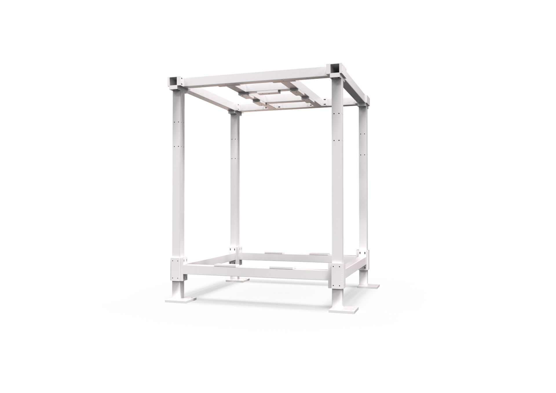
For parallel robot cells specifically, we have worked on mounting frame design and structural integration, including the frame shown in this article. That work sits at the point where robot selection meets structural engineering — the point where most integration problems are actually created.
We integrate robot platforms from established manufacturers and take responsibility for how they are applied. The model selection, the frame design, the vision mounting, and the commissioning are treated as one problem, because on a high-speed cell they behave as one problem.
Our application coverage includes handling, loading and unloading, palletizing, spraying, and welding. For applications outside that scope, we say so plainly and confirm with our engineers rather than assume.
Frequently Asked Questions
How stiff does a parallel robot mounting frame need to be?
There is no single number, because the requirement depends on the robot's reach, payload, acceleration, and the accuracy the application needs. The practical approach is to evaluate stiffness in the direction of dominant motion, and to compare the frame's natural frequency with the robot's motion frequency. A frame that is very stiff vertically but soft horizontally will still produce accuracy loss during horizontal moves.
What causes vibration in a high-speed pick-and-place cell?
Vibration in these cells usually comes from three sources: the robot's own acceleration and deceleration forces, the settling behaviour of the structure after each move, and external sources such as adjacent equipment or floor transmission. The first is inherent to the motion profile. The second is a frame design issue. The third is a site and isolation issue. Identifying which source dominates is the first step in fixing it.
Should the vision camera be mounted on the robot or on the frame?
In most high-speed pick-and-place cells, the camera is mounted to the frame or to a structure that references the same coordinate system as the pick and place positions. Mounting the camera to the robot can work for some applications, but it adds moving mass and introduces a different set of alignment issues. The decision should be made based on what the vision system is measuring relative to.
How do you handle thermal drift in a continuously running cell?
Thermal drift is managed through a combination of design and procedure. Symmetric structures expand more predictably than asymmetric ones. A warm-up routine brings the cell to operating temperature before production. A re-referencing procedure — using a known reference point — restores alignment at defined intervals. The specific approach depends on the accuracy the application requires.
Can a parallel robot be integrated into an existing production line?
Yes, and this is a common integration scenario. The main considerations are the interface to the existing conveyor or feed system, the available floor space and floor construction, the guarding strategy, and how the new cell's control system communicates with the existing line. These are integration questions rather than robot questions, and they are usually resolved during the specification phase.
What information is needed to specify a mounting frame?
At minimum: the robot model and its mass, the payload and acceleration profile, the required accuracy, the vision mounting requirements, the floor construction at the installation site, and the guarding and access requirements. Providing these together allows the frame and the cell to be designed as one system rather than assembled from separate decisions.
Does YGT Robot provide the robot body as well as the integration?
YGT Robot's role is system integration, application solutions, on-site service, and project delivery. We integrate robot platforms from established manufacturers and take responsibility for the cell as a whole — frame, mounting, vision integration, guarding, and commissioning. Robot body manufacturing is not our role.
Related Products
- BRTHC100501A parallel robot workstation — 5 kg payload, 1000 mm arm reach, ±0.05 mm accuracy, 125 kg unit weight, 35 kVA power capacity.
- BRTHC100502A parallel robot workstation — 5 kg payload, 1000 mm arm reach, ±0.05 mm accuracy, 110 kg unit weight, 20 kVA power capacity.
Both models are supplied as workstations and are typically integrated into a cell with a purpose-designed mounting frame. For applications requiring CE certification or explosion-proof construction, confirm the specific configuration with our engineers before specifying.
Talk to Us About Your Cell
If you are specifying a high-speed pick-and-place cell and the frame, vibration, or vision alignment questions are still open, the useful next step is a short technical conversation — not a quotation. Tell us the part, the cycle time target, the robot you are considering, and the floor you are installing on. We will tell you what the structural integration needs to address, and where we need more information before we can answer.