Robot Workcell vs Standalone Robot: A Buyer's Checklist for Specifying a Complete Integrated Cell

The gap between a robot purchase and a working cell
A purchase order for a six-axis robot is straightforward. The arm arrives, it is mounted, it moves. What it does not do on its own is hold the part, reach the spindle, protect the people around it, talk to the machine tool, or prove that it can run at rate. Those functions belong to the workcell—the system of fixture, end-of-arm tooling, part handling, safety, controls, and acceptance criteria that surrounds the arm.
Buyers who specify only the robot often discover the gap later, during commissioning, when the fixture is being reworked, the gripper is dropping parts, the PLC handshake is incomplete, or the safety enclosure is waiting on a risk assessment. The purpose of this checklist is to move those decisions earlier, into the specification stage, where they can be priced, scheduled, and verified.
Why specify the cell, not just the arm
Automation delivers value through repeatability, stable quality, long-term cost reduction, and production flexibility—but only when the whole system is designed around the process. A robot with excellent repeatability will not produce consistent parts if the fixture allows the workpiece to shift. A fast arm will not raise output if the gripper cannot establish a reliable grasp. A well-guarded cell will not run if the controls handshake between the robot and the machine tool is incomplete.
Specifying the integrated cell also changes the commercial conversation. Instead of comparing arm specifications in isolation, buyers compare system capability: cycle time at the required quality level, changeover effort, operator interface, safety compliance, and the support arrangement after handover. That is the comparison that matters on the shop floor.
What a complete robot workcell includes
The table below is a practical breakdown of the subsystems that should appear in a workcell specification. It is not a universal template—smaller cells may combine or omit elements—but every item should be consciously included or consciously excluded, with the reason recorded.
| Subsystem | What it does | What to specify |
|---|---|---|
| Robot arm | Provides motion and reach | Payload, reach, repeatability, mounting position, controller model |
| End-of-arm tooling (gripper, vacuum, welding torch, spray gun) | Interfaces with the workpiece or process | Gripping method, part weight and geometry, vacuum or force requirements, tool change needs |
| Fixture / workholding | Locates and holds the part repeatably | Locating datum, clamping method, load/unload access, chip and coolant clearance |
| Positioner / workpiece manipulator | Presents the part to the robot or process | Payload, axes, synchronization with robot, indexing accuracy |
| Part feeding and exit | Delivers parts in and out of the cell | Magazine, conveyor, pallet, or bin arrangement; buffer capacity; reorientation needs |
| Safety enclosure and guarding | Protects operators and satisfies machinery safety requirements | Fencing, interlocked doors, light curtains, area scanners, emergency stops, risk assessment |
| Controls and handshaking | Coordinates robot, machine tool, and peripherals | PLC platform, fieldbus or I/O interface, sequence logic, fault recovery, HMI |
| Machine tool or process equipment interface | Ties the cell to the production equipment | Door and chuck signals, program selection, in-cycle gauging, spindle interlocks |
| Acceptance testing | Proves the cell meets the specification | Test plan, part samples, cycle time measurement, quality criteria, run-off duration |
| Documentation and training | Supports operation and maintenance | Electrical drawings, spare parts list, operating procedures, operator and maintenance training |
Customer problem: where standalone robot projects go wrong
In practice, the failure modes of a standalone robot purchase are predictable. The arm is selected on payload and reach, which is necessary but not sufficient. Then the following questions surface:
- Who designs the gripper, and against what part tolerance?
- Who confirms that the fixture can hold the part against cutting forces without deflection?
- Who writes the sequence logic, and who owns the handshake between the robot and the CNC or press?
- Who performs the risk assessment, and to which standard?
- Who proves cycle time, and on which parts?
If these questions are answered by different parties after the purchase order, the project acquires interfaces—technical and contractual—that are difficult to close out. Specifying the cell as a single integrated scope keeps those interfaces inside one design and delivery process.
Solution logic: how an integrated cell is specified
A practical specification process moves from the process outward to the equipment, not the reverse.
- Define the process requirement. Part family, material, tolerance, surface finish, cycle time target, and annual volume. Include the parts that are difficult, not only the representative part.
- Map the material flow. How parts arrive, how they are oriented, how they are removed, and what happens to scrap, chips, and coolant.
- Fix the workholding concept. Locating datums, clamping forces, access for loading, and clearance for the tool. The fixture is usually the largest source of repeatability error in a cell.
- Select the end-of-arm tooling. Gripping method follows from part geometry, weight, and surface sensitivity. Vacuum, magnetic, mechanical, or process tooling each impose different requirements on the robot and the controls.
- Size the robot against the real load. Payload includes the tooling and the part, plus dynamic effects during acceleration. Reach must cover the working envelope with margin, not exactly to the farthest point.
- Design the safety concept. Risk assessment, guarding, interlocks, and operator access for loading, inspection, and maintenance.
- Define the controls architecture. Which controller coordinates the cell, which fieldbus or I/O is used, what the fault recovery sequence is, and how the operator interacts with the HMI.
- Agree the acceptance test. Parts, cycle time, quality criteria, run-off duration, and the conditions under which the test is performed.
Key selection factors
Payload and reach
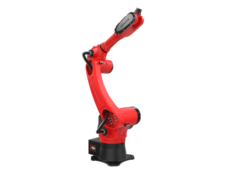
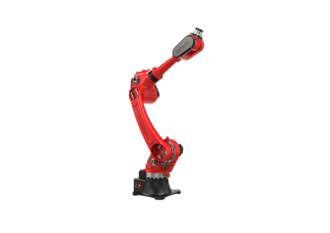
Payload must be calculated with the end-of-arm tooling and the workpiece, and with a margin for dynamic loads. Reach should be checked against the actual working envelope, including the fixture, the machine tool spindle, and the load/unload positions. For reference, the BRTIRUS1510A six-axis robot carries a 10 kg payload with a 1587 mm arm reach, and the BRTIRUS1820A carries a 20 kg payload with a 1895 mm reach; both are quoted at ±0.05 mm repeatability in the manufacturer's selection data. These figures are starting points for sizing, not a substitute for a full load calculation.
Repeatability and accuracy
Repeatability describes how consistently the robot returns to a taught position. Accuracy describes how close that position is to the intended position. For machine tending, the fixture and the tooling usually dominate the achievable part tolerance, so the robot's repeatability figure should be read together with the workholding concept.
End-of-arm tooling
Gripper design is where many cell projects succeed or fail. For pick-and-place and machine tending, the relevant questions include grasp stability, part orientation, surface protection, and whether the tooling can tolerate part-to-part variation. Vacuum handling brings its own considerations—vacuum build-up, vacuum retention, vacuum loss, leakage at the suction cups, double-sheet detection, and part slip—which should be addressed in the tooling specification and the acceptance test.
Fixture and positioner
Fixtures should be specified with locating datums, clamping method, and access for loading. Positioners add axes that present the part to the robot or the process; they need to be specified for payload, indexing accuracy, and synchronization with the robot program.
Safety and compliance
Safety is a system property, not an accessory. The specification should reference the applicable machinery safety requirements, the risk assessment method, and the guarding concept. For CE-marked projects, the robot's own conformity documentation is one input; the cell as a whole requires its own assessment.
Controls and handshaking
The controls architecture determines how the robot, the machine tool, and the peripherals coordinate. Buyers should specify the PLC platform, the preferred fieldbus or I/O interface, the sequence logic, fault recovery behavior, and the operator interface. Where a particular fieldbus is required, confirm the native support and any gateway or protocol conversion needed—this is a common source of late-stage integration work.
Acceptance testing
The acceptance test is the point at which the specification becomes verifiable. It should define the part samples, the cycle time measurement method, the quality criteria, the run-off duration, and the conditions of the test. A cell that has not been tested against agreed criteria is not yet a delivered cell.
After-sales support and documentation
Industrial cells run for years. The specification should cover spare parts, documentation, operator training, maintenance access, and the response arrangement for technical support.
YGT experience
YGT Robot (Guangdong Yigaite Intelligent Technology Co., Ltd.) works as an integration and application provider: we analyze the customer's process, select the appropriate robot platform, and integrate the robot with fixtures, end-of-arm tooling, safety systems, and controls into a working cell. Our declared application scope covers handling, machine tending, palletizing, spraying, and welding. Robot models used in our projects are sourced from BORUNTE; the model specifications are the manufacturer's, while the cell design, integration, and site delivery are our scope.
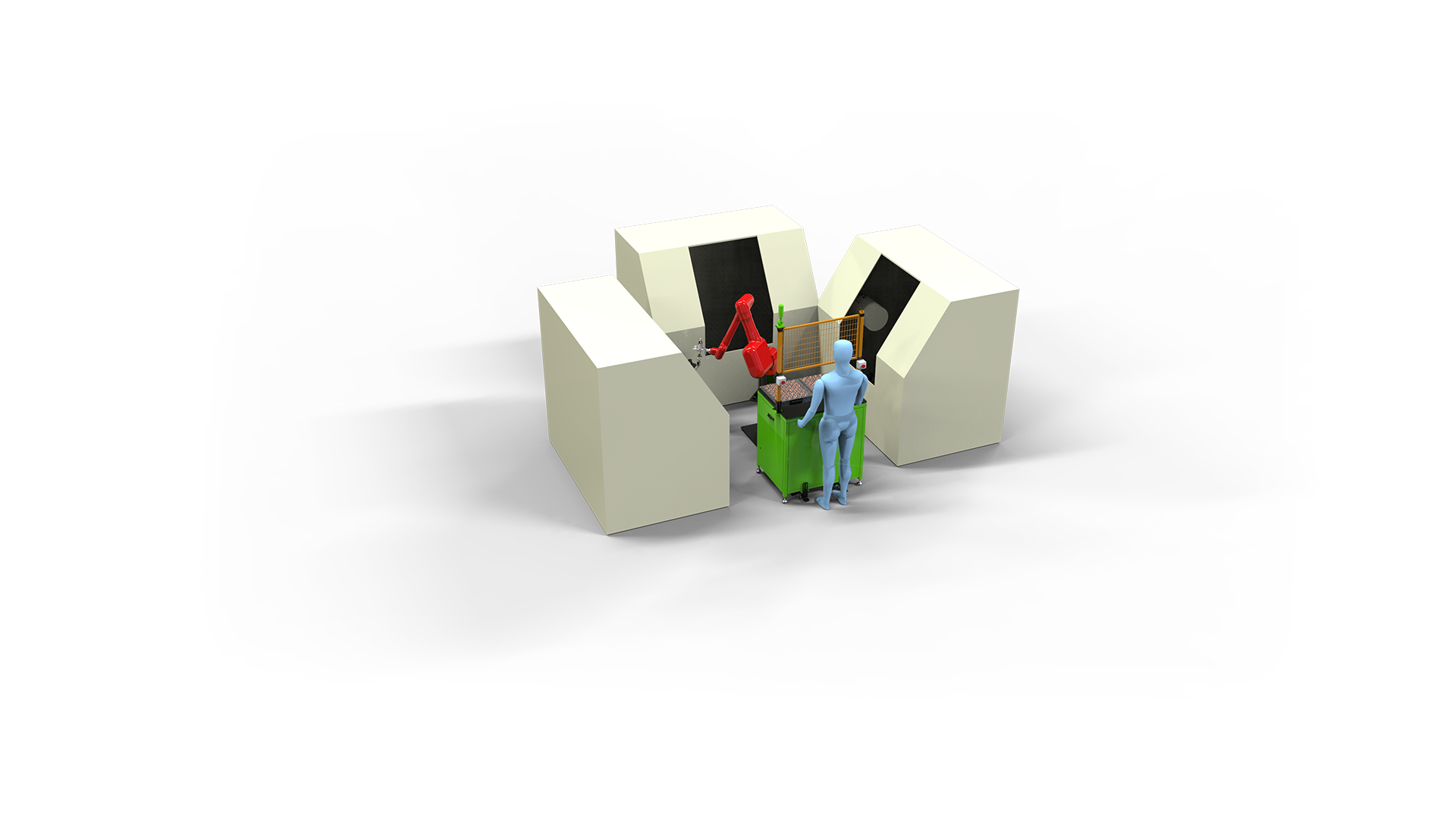
A representative example is a CNC machine tending project in which a BRTIRUS1510A six-axis robot serves three CNC machines—a one-robot-to-three-machine configuration. Projects of this type require the robot, the machine tool interfaces, the part handling, and the safety concept to be designed together, because the value of the cell comes from the coordination rather than from the arm alone.
Where a requirement falls outside our confirmed application scope—for example, deburring, grinding, polishing, gluing, vision sorting, laser cutting, or assembly—we do not assume support. We confirm the requirement with our engineers and define the scope before quoting.
FAQ
What is the difference between a robot and a robot workcell? A robot is the arm and its controller. A workcell is the complete production system around the arm: fixture, end-of-arm tooling, part feeding, safety enclosure, controls handshaking, and acceptance testing. The cell is what produces parts.
Can I buy the robot separately and integrate it myself? Yes, if you have the engineering resources for fixture design, tooling, safety, and controls integration. The risk is that the interfaces between these subsystems are resolved late, during commissioning, when changes are most expensive.
What should be included in a workcell acceptance test? At minimum: the part samples used, the cycle time measurement method, the quality criteria, the run-off duration, and the conditions of the test. The test should be agreed before the purchase order, not after installation.
How do I specify the controls handshake between the robot and my machine tool? Specify the PLC platform, the fieldbus or I/O interface, the sequence logic, and the fault recovery behavior. If your plant standard requires a fieldbus that the robot does not support natively, confirm whether a gateway or protocol conversion is acceptable and who supplies and commissions it.
Does the robot's CE marking cover the whole workcell? No. The robot's conformity documentation covers the robot. The integrated cell requires its own risk assessment and conformity assessment as a machine assembly.
What payload margin should I allow? The payload calculation should include the end-of-arm tooling, the workpiece, and dynamic effects during acceleration. A margin is advisable, but the correct figure depends on the motion profile; it should be calculated rather than assumed.
Can YGT supply the robot only, or only the integration? Our role is integration and application. We select the robot platform as part of the cell design and integrate it with the fixture, tooling, safety, and controls. The scope of each project is defined during the technical review.
Related products
- BRTIRUS1510A six-axis robot — 10 kg payload, 1587 mm reach, ±0.05 mm repeatability, used in CNC tending and handling applications.
- BRTIRUS1820A six-axis robot — 20 kg payload, 1895 mm reach, ±0.05 mm repeatability, for higher-payload handling and tending tasks.
Next step
If you are specifying a robot workcell, the most useful first step is a process review: part family, cycle time target, material flow, and the machine tools involved. Send us the process details and we will respond with a scope discussion covering the robot platform, fixture and tooling concept, safety approach, controls interface, and acceptance criteria—before any commercial proposal.