Specifying a BRTIRUS1510A Six-Axis Robot Cell for Insert Loading and Over-Molding: A Procurement FAQ

The question behind the questions
Most insert over-molding projects do not fail at the robot. They fail at the interfaces around it: how the insert arrives at the pick point, whether the end-of-arm tool can physically enter the mold without colliding with leader pins or ejector hardware, how the molded part leaves the cavity without being dropped, and whether the cell can actually keep pace with the press rather than the other way around.
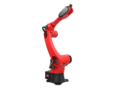
This article is written for the stage where a molder has decided automation is worth investigating and now needs to specify a cell — not to be sold a robot. The BRTIRUS1510A is a six-axis machine with a 10 kg payload, 1,587 mm arm reach, and ±0.05 mm repeatability, integrated by YGT Robot (Guangdong Yigaite Intelligent Technology Co., Ltd.) into injection molding cells for insert loading and over-molding work. Below are the questions buyers actually raise in that specification phase, with the engineering considerations behind each.
Why automate insert loading at all
Insert over-molding has a structural problem that has nothing to do with labor cost: the insert must be positioned identically every cycle, and the window in which it can be placed is defined by the mold, not by the operator. Manual loading introduces variation in insert depth, tilt, and seating force — variation that shows up later as flash, short shots around the insert, or inserts that pull out under load.
Automation addresses four things that matter to a molder's economics:
- Repeatable insert seating. The same insertion path, the same depth, the same force profile, every cycle.
- Mold protection. A controlled entry path reduces the risk of an insert or tool crashing into cavity steel.
- Press utilization. Loading and unloading inside the mold-open window is what determines whether the robot adds capacity or becomes a bottleneck.
- Operator distance from the mold area. Insert loading puts hands inside a closing mold; removing that exposure is a safety argument as much as a cost one.
What automation does not automatically deliver is a shorter cycle. That depends entirely on whether the cell is specified against the press, which is the subject of most of the questions below.
The specification questions, in the order they usually arise
1. How should the insert be presented to the robot?
This is the first decision and it constrains everything downstream. The common options:
| Presentation method | Typical fit | Main constraint to check |
|---|---|---|
| Tray / nest magazine | Small to medium inserts, moderate volumes, multiple insert variants | Nest repeatability and tray changeover time; operator loading frequency |
| Bowl or step feeder with escapement | Small, geometrically simple inserts, high volume | Orientation reliability; jamming on thin or asymmetric parts |
| Inline conveyor with locating nests | Inserts arriving from an upstream process | Nest position tolerance at the pick point; accumulation logic |
| Magazine in the mold area | Short travel distance, tight cycle targets | Magazine must not obstruct mold access or robot path |
For a 10 kg payload machine, the insert weight is rarely the limiting factor — the gripper, the insert-presentation hardware on the arm, and the dynamic loads during entry usually are. The practical check is total tooling mass plus insert mass against payload, with margin for acceleration.
2. Will the arm actually fit in the mold area?
The 1,587 mm reach is a working envelope figure, not a guarantee of mold access. What determines feasibility is the geometry of the entry path:
- Distance from robot base to the cavity. Reach must cover the pick point, the mold entry, the insert placement point, and the part exit — not just the farthest of these.
- Entry attitude. The wrist orientation needed to place an insert perpendicular to the cavity face often consumes more of the envelope than the straight-line distance suggests.
- Obstructions. Leader pins, ejector plates, water manifolds, hot-runner cabling, and the clamp unit itself all sit inside the nominal working volume.
- Mold-open window. The robot must complete entry, placement, withdrawal, and part removal within the time the mold is open — the reach check and the timing check are the same check.
This is the point where a reach diagram is not sufficient and a layout study is. A cell that fits on paper but requires an awkward wrist attitude will show up as reduced speed or as interference in production.
3. How is the molded part retained and removed?
Part retention is where insert over-molding cells most often underperform, because the part is not a simple shape — it has an insert molded into it, often with a different surface finish and a different rigidity than the surrounding resin.
Retention approaches, in rough order of application:
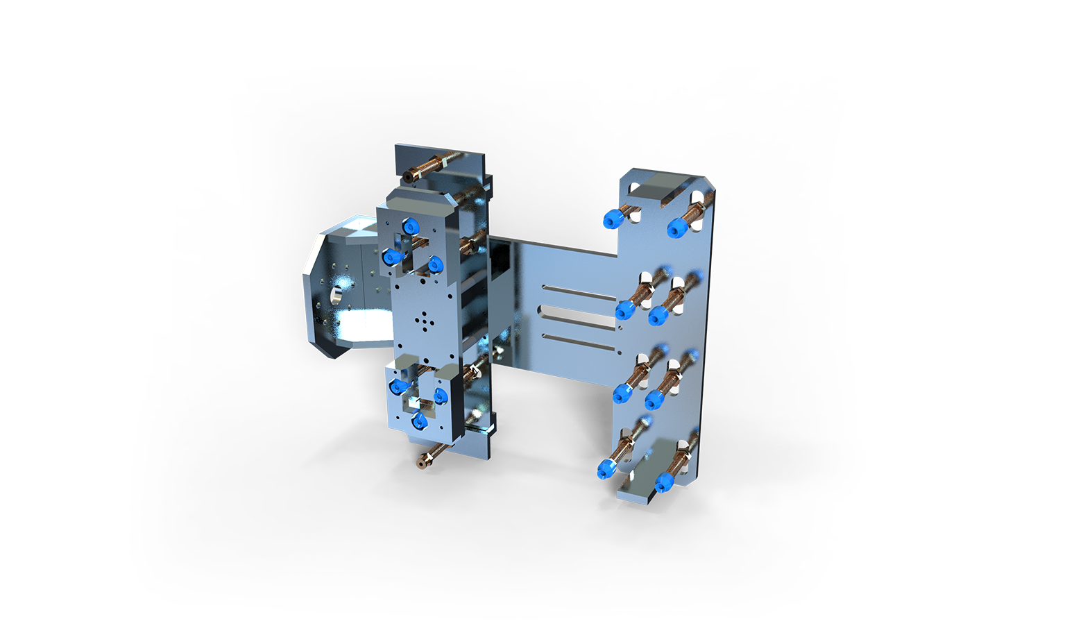
- Vacuum on a compliant cup or pad. Works well on flat or gently curved surfaces; sensitive to surface texture, draft, and any porosity in the molded surface. Vacuum loss during transfer is the classic failure mode.
- Mechanical grippers on defined features. More reliable on parts with ribs, bosses, or a gate stub to grip, but the gripper must not mark a cosmetic surface.
- Combination — mechanical location with vacuum assist. Common where the part is large or where the insert creates an unbalanced mass.
- Ejector-assisted release plus robot pick. The mold does part of the work; the robot only has to capture and transfer.
Whichever is chosen, the specification question is not "can it pick the part" but "what happens on the cycle where it does not" — see the scrap question below.
4. Can the cell match the press cycle?
Cycle-time matching is usually discussed as robot speed. In practice it is a budget across four segments, and the robot is only one of them:
| Cycle segment | What sets it | Where the time is lost |
|---|---|---|
| Mold open and robot entry | Press open time, safety interlock, robot path | Conservative entry paths, unnecessary waypoints |
| Insert pick and placement | Insert presentation distance, gripper actuation | Presentation point too far from mold; slow gripper |
| Part removal | Retention method, part size, exit path | Vacuum build/release time; part dragging on cavity |
| Robot exit and mold close | Path clearance, interlock confirmation | Waiting on signals rather than on motion |
The realistic target is a cell that completes its work inside the mold-open window with margin, not one that runs the robot at maximum speed. A robot specified to just barely fit the window leaves no room for the cycle where an insert is slightly out of position, the vacuum is marginal, or the press runs a variant with a longer cooling time.
5. What happens to rejects and scrap?
This question is often deferred to commissioning and then becomes expensive. Insert over-molding produces several distinct reject classes, and they need different handling:
- Insert placement faults — insert missing, tilted, or not fully seated. Detected by sensing at the gripper or by in-mold verification.
- Short shots and flash around the insert — a molding fault, but the robot cell is where the part is segregated.
- Part retention failure during transfer — the part is dropped mid-cycle. Where it lands matters: on the tie bars, in the clamp area, or on the floor.
- Insert feed faults — double feeds, misoriented inserts, empty nests.
The specification decision is whether the cell segregates rejects automatically (a reject chute or bin with confirmation) or relies on the operator. For a cell running unattended, automatic segregation with a signal back to the press or the line controller is generally the difference between a cell that runs and a cell that needs attention.
Where the integration work actually sits
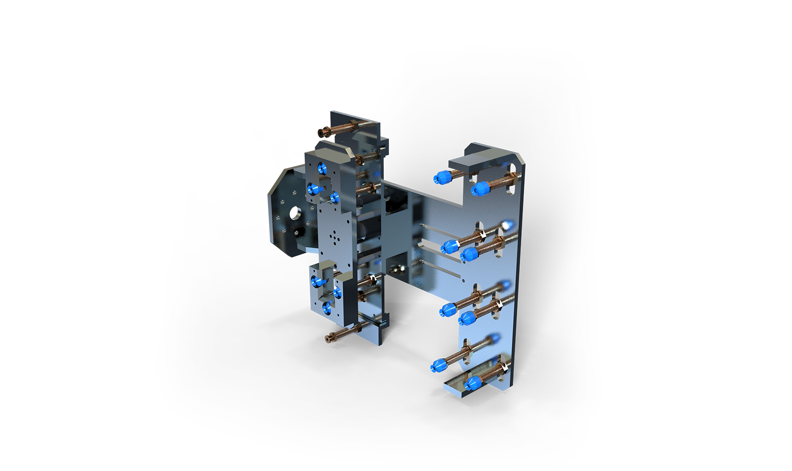
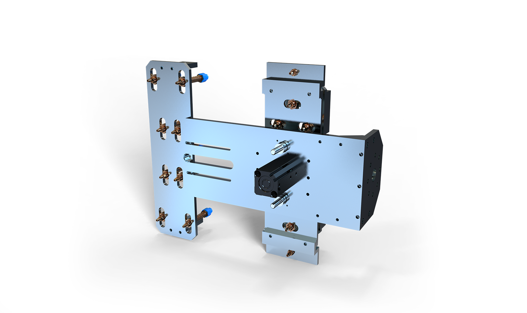
A robot model is a component. The cell is the integration: the end-of-arm tooling, the insert presentation hardware, the interface to the injection molding machine's sequence and safety circuit, the reject handling, and the guarding.
The BRTIRUS1510A is manufactured by BORUNTE; YGT Robot's role is the application and integration side — specifying the cell layout against the mold and press, building or sourcing the tooling, and commissioning the sequence so the robot and the molding machine behave as one system. That distinction matters at procurement because the questions above are integration questions, not catalogue questions.
On the machine itself, the confirmed specification points relevant to this application are: six-axis configuration, 10 kg payload, 1,587 mm arm reach, ±0.05 mm repeatability, 152 kg mass, 5.06 kVA power capacity, and CE conformity. Handling, loading/unloading, palletizing, spraying, and welding are declared application areas; insert loading and over-molding cells fall within the handling and loading scope. The model is not explosion-proof — the BORUNTE range includes a separate explosion-proof model — so any application requiring that rating needs a different selection.
A short note on the numbers buyers ask for
Procurement teams reasonably ask for cycle-time improvements, labor reduction, and yield figures from comparable projects. Those numbers are project-specific: they depend on the press, the mold, the insert, the tooling, and the production schedule. Quoting a generic percentage would be misleading, and this article deliberately does not. What can be stated is the specification logic above and the confirmed machine parameters; the performance figures come from a layout study against your actual mold and press.
What to prepare before a specification discussion
If you are evaluating an insert over-molding cell, having these ready shortens the engineering cycle considerably:
- Mold drawings, including cavity layout, leader pin positions, and ejector arrangement
- Press model, tie-bar spacing, platen size, and minimum/maximum mold height
- Insert drawings with material, weight, and any orientation-critical features
- Target cycle time and the current mold-open time
- Part drawings with cosmetic surfaces marked
- Reject classes you currently see and how they are handled
- Available floor space and the planned operator position
With those, the questions above become a layout rather than a discussion.
FAQ
Q: Can the BRTIRUS1510A handle inserts and finished parts in the same cycle? A: The 10 kg payload covers the combined mass of the end-of-arm tooling, the insert, and the molded part in most insert over-molding applications, but the check is against total tooling mass plus both loads with acceleration margin — not against the insert alone. The tooling design determines whether a single gripper handles both or whether a dual-function end effector is needed.
Q: How close does the robot need to be to the mold? A: Close enough that the full entry, placement, and withdrawal path sits inside the 1,587 mm reach with margin, and far enough that the robot base and cabling do not obstruct mold changes or maintenance access. The practical constraint is usually the mold-open window rather than the reach itself.
Q: What repeatability is needed for insert placement? A: The robot's ±0.05 mm repeatability is generally finer than the insert-to-cavity tolerance requires. The dominant variation in an insert cell usually comes from the insert presentation nest and the gripper, not from the arm — which is why presentation hardware deserves as much specification attention as the robot.
Q: Can the cell run unattended? A: That depends on the reject handling and insert feed design, not on the robot. A cell with automatic reject segregation, insert-presence sensing, and a reliable feed escapement can run with limited attendance; a cell that relies on an operator to notice a dropped part generally cannot.
Q: Is the BRTIRUS1510A suitable for cleanroom molding? A: Cleanroom suitability is a cell-level question covering the robot, the tooling, and the guarding, and it is not a declared specification point for this model. It should be confirmed with YGT engineers against the specific cleanroom class and the molding environment.
Q: What about static charge or sensitive inserts? A: Static control is a tooling and material-handling consideration rather than a robot specification. Where inserts are static-sensitive, the end effector and presentation hardware are where the mitigation is designed.
Q: How is the robot interfaced to the injection molding machine? A: The interface covers the mold-open and mold-close sequence, the safety interlock, and the reject signal. The specific interface arrangement depends on the molding machine's controller and is confirmed during the cell design, not assumed from the robot side.
Q: Can the same cell run multiple insert variants? A: Yes, where the presentation hardware and tooling support changeover. The specification question is changeover time and whether variant selection is handled by the robot program, the press, or the line controller — this should be decided early because it affects the tooling design.
Next step
If you are at the stage of sizing an insert over-molding cell, the useful next step is a layout review against your mold and press rather than a product quotation. Send the mold drawing, press specification, and insert details, and the engineering team can confirm whether the BRTIRUS1510A envelope and payload fit your application, what tooling approach is appropriate, and where the cycle-time constraints sit.
Published by YGT Engineering Team · YGT Robot (Guangdong Yigaite Intelligent Technology Co., Ltd.) · ygtrobot.com