Specifying a Six-Axis Robot Cell for Insert Extraction and Unscrewing/De-Molding: A Sourcing FAQ


Why insert extraction and de-molding are a robot-cell problem, not just a gripper problem
Insert extraction looks simple on paper: grip the insert, pull it out, drop it in a bin. In practice, it is one of the more demanding pick-and-place duties in an injection molding plant. The insert is often seated with interference, sometimes bonded by flash or residual melt, and frequently still hot. The extraction stroke must be coaxial with the insert axis, or the insert cocks in the bore and either jams or scores the mold. Unscrewing adds a second axis of motion and a torque profile that changes as the thread releases. De-molding adds a third constraint: the part must leave the mold without dragging, and the cell must know whether it actually did.
A six-axis robot is a good kinematic match for this duty because it can present an end-of-arm tool at an arbitrary orientation, combine a linear extraction with a rotary unscrewing motion, and then reorient for drop-off. But the robot is only the motion platform. The cell behavior that determines whether the station runs unattended — thread engagement, torque reaction, ejection confirmation, and cycle-time synchronization with the press — lives in the tooling, the sensing, and the integration logic.
This guide is organized as a sourcing FAQ, because that is how these cells are actually specified: engineering asks a series of questions, and each answer constrains the next.
The decision sequence: what to fix first
Most failed specifications start with the robot model. A more reliable sequence is:
- Part and insert geometry — insert type, thread form, insertion depth, draft, and whether the insert is molded-in, heat-staked, or pressed.
- Extraction force and torque — measured, not estimated, ideally with a force gauge on a manual pull and a torque wrench on a manual unscrew.
- End-of-arm tooling concept — grip method, compliance, torque reaction path, and whether unscrewing is done by the robot wrist or by a spindle on the tool.
- Sensing and confirmation — how the cell proves extraction, thread engagement, and part release.
- Cycle-time budget — the cell's motion time versus the press open window.
- Robot selection — payload, reach, repeatability, and controller interface, sized from the above.
Reversing this order is the most common cause of a cell that works in commissioning and drifts in production.
FAQ: torque-reactive end-of-arm tooling
Should the robot wrist generate the unscrewing torque, or should the tool carry its own spindle?
Both are used. Wrist-driven unscrewing is simpler and lighter, but it puts the reaction torque through the robot's wrist and arm. For small inserts at low torque, this is usually acceptable. For larger inserts, or where the thread is prone to galling, a dedicated spindle on the tool with a reaction bracket is often the better choice: the spindle absorbs the torque, the robot only positions and translates. The trade-off is tool weight and complexity, which consumes payload and can reduce access into deep mold pockets.
How is reaction torque handled if the wrist drives the screw?
The tool needs a compliant coupling that allows the socket to self-align to the thread axis, plus a mechanical stop or a torque-monitored wrist motion so the reaction is taken by the robot structure rather than by the insert. A rigid socket on a rigid wrist is a reliable way to cross-thread inserts.
What compliance is needed for thread engagement?
Enough lateral and angular compliance to absorb the mismatch between the robot's programmed pose and the actual insert axis, which varies with mold temperature and part shrinkage. A floating socket holder with a few millimeters of lateral travel and a few degrees of angular freedom is typical. The compliance should be stiff enough in torsion that it does not wind up and release unpredictably when the thread breaks free.
Does the tool need a torque sensor?
Not always, but torque monitoring is the cheapest way to detect cross-threading and bottoming. A spindle with an adjustable torque clutch gives a mechanical limit; a current- or torque-monitored spindle gives a signal the cell can act on. For unattended operation, a signal is preferable to a clutch, because the cell can stop and alarm rather than slip silently.
FAQ: thread engagement and extraction confirmation
How does the cell know the socket engaged the insert before torquing?
Engagement is usually confirmed by a short slow-speed rotation with torque monitoring: if torque rises within the first fraction of a turn, the socket is engaged; if the spindle turns freely, it is not. Some cells add a proximity or air-gap check at the tool to confirm the socket is seated over the insert.
How is extraction verified?
Three signals are commonly combined: a stroke or position check (the tool reached the extraction depth), a force or current signature (the pull met the expected resistance), and a part-present sensor at the drop-off point (the insert actually left the tool). Any one alone can be fooled — a stuck insert can still show a completed stroke, and a dropped insert can still show a completed stroke if the tool released early.
What happens if the insert does not come out?
The cell should stop and alarm rather than retry blindly. A retry on a jammed insert can drive the tool into the mold or shear the insert. A common strategy is a single controlled re-seat and re-pull at reduced force, then an operator call.
FAQ: part ejection and drop detection
How is part release confirmed after de-molding?
Drop detection is usually done with a light curtain, a photoelectric sensor across the drop chute, or a vision check at the drop-off position. The choice depends on part size, drop height, and whether the part can bounce back into the cell. For small parts, a chute-mounted sensor is often more reliable than a vision check, because the part is moving fast and can be occluded by the tool.
What if the part sticks in the mold?
The cell needs an ejection-confirmation signal from the mold or press before it enters. If the part is still in the cavity, the robot should not attempt a pick. This is an interlock with the press controller, not a robot-side decision.
How is a dropped part handled without stopping the cell?
For high-volume cells, a drop-confirmation sensor with a reject path is common: the part is released over a chute, the sensor confirms passage, and a missed confirmation diverts the next cycle to a reject bin and raises an alarm. The cell continues, but the event is logged.
FAQ: cycle-time matching
The cell's cycle time is rarely the robot's motion time alone. It is the sum of:
- approach and orientation into the mold pocket;
- grip and engagement;
- extraction stroke;
- unscrewing rotation (if applicable);
- retract and reorient;
- travel to drop-off and release;
- return to the ready position before the press closes.
For a cell synchronized with an injection molding machine, the binding constraint is usually the press open window, not the robot's maximum speed. A cell that is 20% faster than the window buys nothing; a cell that is 5% slower forces the press to wait. The practical approach is to measure the manual or existing cycle, add the sensing and confirmation steps, and then check whether the robot's rated speed and the tool's rotation speed fit inside the window with margin for variation.
Unscrewing is often the hidden cycle-time driver. Thread pitch and rotation speed set the unscrew time; a multi-start thread or a short engagement reduces it, a fine thread or a long engagement increases it. If the unscrew time alone approaches the press window, a spindle on the tool that can rotate during the robot's approach is worth considering.
Comparison table: tooling and sensing options
| Decision | Option A | Option B | Typical fit |
|---|---|---|---|
| Unscrewing drive | Robot wrist rotation | Spindle on end-of-arm tool | Wrist for small, low-torque inserts; spindle for larger inserts or galling-prone threads |
| Torque reaction | Robot structure via compliant coupling | Mechanical reaction bracket on tool | Bracket where torque is high or wrist loading is a concern |
| Thread engagement sensing | Torque rise on slow rotation | Proximity / air-gap check at socket | Torque rise as default; add proximity for blind or deep pockets |
| Extraction confirmation | Stroke/position check | Force or current signature | Combine both for unattended cells |
| Drop detection | Photoelectric sensor at chute | Vision check at drop-off | Chute sensor for small fast parts; vision for large or orientation-critical parts |
| Insert reuse handling | Direct drop to reuse bin | Inspect-then-sort | Direct drop where insert condition is stable; inspect-then-sort where flash or deformation is possible |
FAQ: insert reuse handling
Can extracted inserts be reused?
Often yes, but the decision is a quality one, not an automation one. Inserts that come out cleanly, without thread damage or deformation, can usually be returned to the feed system. Inserts that gall, deform, or carry flash should be segregated. The cell can support either policy, but the policy has to be defined before the tooling is designed, because it determines whether the cell needs an inspection step and a second drop-off position.
How does the cell separate reusable from non-reusable inserts?
Simple segregation is by extraction result: a clean extraction goes to the reuse bin, an alarm condition goes to the reject bin. More thorough segregation adds a vision or gauging check at drop-off, which costs cycle time and floor space. For most cells, result-based segregation is sufficient; the inspection step is added where insert cost or quality risk justifies it.
What about inserts that are still hot?
Hot inserts can deform under grip force and can stick to the tool. The tooling should account for thermal expansion and for the possibility that the insert cools and shrinks onto the socket. A brief air blast or a dwell before release is sometimes used. This is a tooling detail, but it affects cycle time and should be settled early.
Key selection factors for the robot platform
Once the tooling and sensing concept is fixed, the robot can be sized. For this class of duty, the relevant parameters are payload, reach, repeatability, and controller interface.
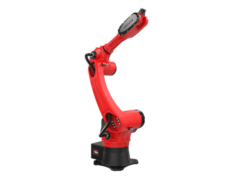
A representative platform for insert extraction and de-molding work is the BRTIRUS1510A six-axis robot, which carries a 10 kg payload, a 1587 mm arm reach, and ±0.05 mm repeatability, with a 5.06 kVA power capacity and a 152 kg robot mass. Those figures matter in this application in specific ways: the payload must cover the tool plus the insert plus any reaction bracket; the reach must cover the mold pocket depth plus the drop-off position without stretching the arm to its limit; and the repeatability supports consistent socket-to-insert alignment, though the compliance in the tool still does most of the alignment work. The model carries CE conformity (DPWD/03/0646/2025, covering 2006/42/EC machinery and 2014/35/EU low voltage) and is not an explosion-proof variant; the explosion-proof option in this range is a separate model. Where the cell sits in a hazardous area, that has to be addressed at the cell level.
Beyond the datasheet, the questions to put to any supplier are: what is the controller's interface to the press and to the tool's spindle and sensors; how are torque and force signals brought into the robot program; and what happens on a mid-cycle alarm. These are integration questions, and they are where a cell either runs unattended or needs an operator standing by.
Where integration experience matters
Insert extraction and de-molding cells are assembled from a robot platform, a custom end-of-arm tool, a spindle or wrist drive, a sensor set, and a control interface to the press. The robot is the most standardized part of that list. The tooling and the integration logic are where the cell is won or lost.
YGT Robot's role in this application is integration and application engineering: selecting the robot platform against the measured force, torque, and reach requirements; designing or specifying the end-of-arm tooling and its compliance and torque reaction; defining the sensing scheme for engagement, extraction, and drop confirmation; and integrating the cell with the press controller and the plant's alarm and logging systems. The robot platform itself is sourced from the manufacturer, and its published parameters are used as given.
This matters to a sourcing team because the specification questions in this guide — torque reaction, thread engagement, drop detection, cycle-time margin — are not answered by a robot datasheet. They are answered by someone who has built the cell.
What to bring to a specification review
A productive review with an integrator usually needs: part drawings with insert locations and thread specification; the measured extraction force and unscrewing torque; the press open window and current cycle time; the insert reuse policy; and the plant's requirements for alarms, logging, and operator intervention. With those in hand, the tooling concept, sensing scheme, and robot platform can be fixed in a single session rather than through several rounds of quotation.