Specifying Robot Cells for CNC Lathe Bar Feeding and Long-Shaft Part Transfer: A Buyer's FAQ


Why this guide exists
Specifying a robot cell for a CNC lathe is not the same as buying a robot. The robot is one component. The cell is a system: the lathe, the bar feeder or magazine, the gripper, the tailstock and chuck envelope, the safety fencing, the controller handshakes, and the sequence logic that keeps all of them in step.
Most of the specification risk sits in the interfaces — not in the robot datasheet. This guide walks through the questions that machining engineers and automation project managers actually raise during cell specification, with the design logic behind each answer.
Start with the part, not the robot
Before any model is discussed, the part geometry has to be pinned down. For bar feeding and long-shaft transfer, four part characteristics drive everything downstream:
- Diameter range and length range — including the shortest and longest variant you realistically expect to run
- Weight per piece — at the heaviest variant, not the nominal one
- Surface condition — ground, turned, cast, or hot-rolled; this decides gripper type
- Tolerance on the finished feature — determines whether the robot can present the part, or whether a secondary locating step is needed
A cell that is specified against the nominal part and then asked to run the extremes is where most commissioning delays come from. Specify to the envelope.
Gripper and tailstock clearance
This is the single most common source of rework in lathe-tending cells.
The tailstock problem
On a lathe running between centres, the tailstock occupies the right-hand end of the spindle axis. The robot must load the workpiece into the chuck, and the tailstock must then advance to support it. If the gripper is still holding the part when the tailstock advances, the two collide.
The design question is: at what point in the sequence does the gripper release, and where does it retract to?
Three approaches are used in practice:
| Approach | How it works | Trade-off |
|---|---|---|
| Load, release, retract, then tailstock advance | Gripper withdraws fully before tailstock moves | Safest; adds a few seconds to cycle |
| Load, tailstock advance to contact, then release | Part is supported by both chuck and tailstock during handover | Faster; requires gripper geometry that clears the tailstock body |
| Load into a spring-loaded centre, release, tailstock advance | Part held by centre during handover | Requires a centre that can take the part weight before clamping |
The right choice depends on shaft stiffness and length-to-diameter ratio. A long, slender shaft that deflects under its own weight needs support during handover; a short, rigid part does not.
Gripper clearance envelope
When specifying a gripper, the clearance question is not just "does it fit between chuck and tailstock" — it is "does it fit at every point in the approach path." The gripper must:
- Pass the chuck jaws in the open position
- Clear the bar feeder push rod or remnant
- Retract without sweeping the tool turret path
- Clear the tailstock body during the travel to and from the load position
A useful specification exercise is to draw the gripper envelope at the load position, the retract position, and the intermediate path, then overlay the lathe's moving elements. This is normally done during cell design, before the robot model is fixed.
Reach and payload for shaft overhang
Reach is measured to the wrong point
Robot reach figures are quoted to the wrist centre, or to a defined point on the flange. What matters for lathe tending is reach to the centre of the gripped part, which is further out by the gripper length plus half the part length.
For a long shaft, this offset can be substantial. A part 800 mm long gripped at its midpoint puts the part centre 400 mm beyond the grip point, and the gripper itself may add 150–250 mm. The effective reach requirement is therefore the distance from the robot base to the load position plus the gripper and overhang offset.
Payload is more than part weight
The rated payload must cover:
- Part weight
- Gripper weight
- Any cable or hose management carried on the wrist
- Dynamic loads during acceleration and deceleration
For a long shaft, the dynamic component is not trivial. When the robot rotates a shaft about its midpoint, the moment of inertia is high, and the torque demand on the wrist axes can approach or exceed the static load case. This is why a part that is comfortably within the payload rating by weight can still be marginal in practice.
Rule of thumb used in cell design: keep the combined static load at or below roughly 60–70% of rated payload when the part has significant overhang, and verify the wrist torque for the actual rotation path rather than relying on the payload figure alone.
Reach versus rigidity
A robot operating near the outer limit of its reach envelope has less structural rigidity than one operating closer to its base. For a long shaft, where the part itself is a lever arm, this matters. Where the geometry allows, position the robot so the load and unload points sit in the middle of the working envelope rather than at the extreme.
Cycle synchronization with the bar feeder
The bar feeder and the robot are two independent systems that must behave as one. The interface between them is where cycle time is won or lost.
The handshake sequence
A typical bar-fed lathe cell runs a sequence like this:
- Bar feeder advances bar to the stop
- Chuck clamps, bar feeder retracts
- Lathe machines the part
- Part-off cycle completes; finished part remains in the chuck or drops to a catcher
- Robot moves to the load position
- Robot grips the finished part; chuck opens
- Robot withdraws the finished part
- Robot loads the next blank (or the bar feeder advances for the next cycle)
- Chuck clamps; robot releases and retracts
- Cycle repeats
The synchronization question is: which system is the master, and where does the robot wait?
If the robot waits for a signal from the lathe before starting its approach, the robot's travel time is added to the cycle. If the robot pre-positions during machining, the travel time is hidden. Pre-positioning is standard practice, but it requires the robot controller to know when the machining cycle will end — which means a reliable part-off or cycle-complete signal from the lathe, not a fixed timer.
Where the time actually goes
| Sequence element | Typical contribution to cycle | Notes |
|---|---|---|
| Robot travel to load position | Significant if not pre-positioned | Hidden if pre-positioned during machining |
| Gripper close and clamp confirmation | Small but non-zero | Sensor confirmation adds reliability at small time cost |
| Chuck open / close | Fixed by lathe | Outside robot control |
| Part withdrawal and transfer | Scales with shaft length | Long shafts take longer to clear the spindle |
| Tailstock advance / retract | Fixed by lathe | Constrains handover window |
For long shafts, the withdrawal and transfer step is the one that grows. A cell designed for short parts will not automatically meet cycle on long ones, even with the same robot.
One-to-one versus one-to-two layouts
This is a layout decision, not a robot decision, and it should be made early.
| Layout | Configuration | Best suited to | Considerations |
|---|---|---|---|
| One-to-one | One robot serves one lathe | Long cycle times; long shafts; high part weight; tight handover windows | Robot utilisation may be low if lathe cycle is long; simplest integration |
| One-to-two | One robot serves two lathes | Short to medium cycle times; small to medium parts; high volume | Robot must be positioned to reach both load points; cycle overlap requires careful sequencing; one lathe stoppage affects the other's rhythm |
How to decide
Work out the robot's busy time per part — travel, grip, transfer, release, retract — and compare it to the lathe's machining time.
- If robot busy time is a large fraction of machining time, one-to-one is the realistic choice. The robot has little idle capacity to give to a second machine.
- If robot busy time is a small fraction of machining time, one-to-two becomes viable, because the robot can service the second lathe during the first lathe's machining window.
For long-shaft transfer specifically, robot busy time tends to be high — long travel distances, longer withdrawal strokes, and slower moves to control shaft deflection. This pushes the calculation toward one-to-one more often than it does for small-part turning.
A second consideration is failure mode. In a one-to-two cell, a robot fault stops two lathes. In a one-to-one cell, it stops one. Where the lathes are running unattended or on a lights-out shift, this is a real operational trade-off, not just a cost calculation.
Key selection factors, summarized
| Factor | What to specify | Why it matters |
|---|---|---|
| Payload | Part + gripper + wrist services, with margin for dynamic load | Prevents wrist overload on high-inertia shafts |
| Reach | To the gripped part centre, including gripper and overhang offset | Prevents unreachable load positions |
| Repeatability | Matched to the lathe's locating tolerance | Determines whether secondary locating is needed |
| Gripper type | Matched to part surface and weight | Prevents slip and surface damage |
| Tailstock clearance | Verified at load, handover, and retract positions | Prevents collision during handover |
| Bar feeder interface | Signal-level handshake, not timer-based | Determines achievable cycle time |
| Layout | One-to-one or one-to-two, based on busy-time ratio | Determines cell throughput and failure mode |
| Controller compatibility | Matched to lathe and bar feeder control platforms | Determines integration effort |
| Safety | Fencing, interlocks, and mode selection to applicable standards | Required for commissioning and operation |
How YGT approaches lathe-tending cell specification
YGT Robot (Guangdong Yigaite Intelligent Technology Co., Ltd.) works as a system integrator and application solution provider for robot automation in machining environments. That means the specification work starts from the part and the process, not from a robot model.
In practice, the engineering sequence we follow is:
- Part and process review — geometry, weight, tolerance, and the operations the cell must perform
- Cell layout — robot position, load and unload points, gripper envelope, and clearance to lathe moving elements
- Gripper and end-effector design — matched to part surface, weight, and handover requirements
- Robot selection — payload, reach, and repeatability verified against the actual load case, including overhang and dynamic effects
- Control and interface engineering — handshake logic between robot, lathe, and bar feeder
- Safety and commissioning — guarding, interlocks, and cycle proving on site
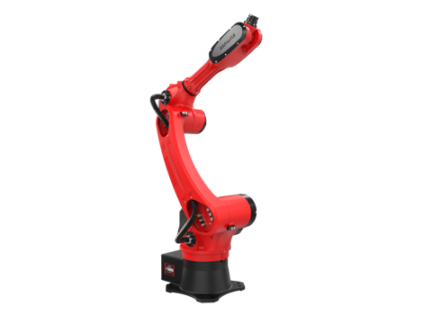
For CNC lathe bar feeding and long-shaft transfer applications, YGT has delivered cells built on the BRTIRUS1510A six-axis robot platform. That model is a 10 kg payload, 1587 mm reach six-axis robot with ±0.05 mm repeatability, and it carries CE conformity verification. It is a robot platform we integrate; the cell design, gripper, interface logic, and commissioning are the integration work.
Where an application falls outside our confirmed scope — for example, certain secondary operations — we will say so and confirm with our engineers rather than assume. That is a deliberate position: it is better to confirm a boundary during specification than to discover it during commissioning.
FAQ
Q: Can one robot serve two CNC lathes for bar feeding?
It depends on the ratio of robot busy time to lathe machining time. If the robot's travel, grip, transfer, and retract time is a small fraction of the lathe cycle, one-to-two is viable. For long-shaft transfer, robot busy time is typically high because travel distances and withdrawal strokes are longer, so one-to-one is more common. The failure mode also matters — a robot fault in a one-to-two cell stops both lathes.
Q: How do I calculate the payload needed for a long shaft?
Add the part weight, the gripper weight, and any wrist-mounted cable or hose management. Then check the dynamic case: rotating a long shaft creates significant inertia, and the wrist torque demand during acceleration can exceed the static load. A common design practice is to keep combined static load at or below roughly 60–70% of rated payload when overhang is significant, and to verify wrist torque for the actual motion path.
Q: What reach figure should I use when specifying?
Use reach to the centre of the gripped part, not reach to the wrist flange. Add the gripper length and the overhang from the grip point to the part centre. For a shaft gripped at its midpoint, the overhang is half the part length.
Q: How does the robot avoid colliding with the tailstock?
By defining the handover sequence explicitly: either the gripper releases and retracts before the tailstock advances, or the tailstock advances to contact while the gripper still supports the part, then the gripper releases. The correct choice depends on shaft stiffness and length-to-diameter ratio. The gripper envelope should be checked at the load position, the handover position, and the retract path.
Q: Should the robot be synchronized to the bar feeder by timer or by signal?
By signal. A timer-based handshake cannot adapt to variation in machining time, and it will either add idle time to the cycle or risk a collision. A cycle-complete or part-off signal from the lathe allows the robot to pre-position during machining and start its approach at the right moment.
Q: What repeatability is needed for lathe loading?
Repeatability should be matched to the locating tolerance of the chuck or fixture. If the chuck self-centres and the part has a chamfer or lead-in, a wider repeatability is acceptable. If the part must seat against a face or a specific feature, tighter repeatability or a compliant gripper may be needed. The robot's repeatability figure is one input; the fixture design is the other.
Q: Can the same cell handle both bar feeding and long-shaft transfer?
Often yes, but the specification must cover both cases. Bar feeding typically involves shorter, repeated parts; long-shaft transfer involves longer parts with greater overhang and different handover requirements. The cell should be specified against the more demanding case, and the gripper and sequence logic should be checked for both.
Q: What happens if my application is outside the confirmed scope?
We will tell you during specification rather than after. Where an operation or interface is not confirmed for a given platform, we confirm with our engineering team before committing. This is part of how we scope integration projects.
Related products
- BRTIRUS1510A Six-Axis Robot — 10 kg payload, 1587 mm reach, ±0.05 mm repeatability, CE conformity verified. Used in YGT lathe-tending and handling cells.
Next step
If you are specifying a lathe-tending cell, the most useful starting point is the part drawing and the process sequence. Send us the part envelope, the lathe model, and the bar feeder or magazine you plan to use, and we will work through the layout, gripper, and interface questions with you.
Request a cell specification review — include part drawings and lathe details for a faster response.