Specifying Robot End-of-Arm Tooling and Gripper Interfaces for Insert Molding, Nut Embedding, and Sprue Picking Cells


The Real Problem: EOAT Is Usually the Last Thing Specified and the First Thing That Fails
Most injection molding automation projects do not fail because the robot was wrong. They fail because the end-of-arm tooling was specified after the robot was chosen, as an accessory rather than as part of the process.
Insert molding, nut embedding, and sprue picking look similar on a plant floor diagram — a robot reaches into a molding machine, picks something, and places it. In practice they are three different gripping problems with three different failure modes:
- Sprue picking is a release problem. The sprue is hot, light, irregular, and often still attached to a runner. Vacuum may not seal; mechanical grip may crush or mark.
- Nut embedding is a placement force and position problem. The insert must be held rigidly, oriented precisely, and often pressed or vibrated into the mold without shifting.
- Insert molding is a dual-handling problem. The cell must remove the finished part and load the insert with the same tool, in the same cycle, without contaminating or misaligning either.
If the EOAT is selected before these three process realities are written down, the cell will run — and then drift.
Why Automate These Cells At All
The justification for automation in molding is rarely headcount alone. It is usually one or more of the following:
- Cycle consistency — a robot inserts and removes at the same moment, every cycle, which stabilizes mold temperature and reduces scrap from early or late ejection.
- Repeatable insert placement — nut and insert position no longer depends on operator feel, which matters most in parts with tight thread or boss tolerances.
- Reduced operator exposure — the mold area is hot, tight, and mechanically hazardous; removing hands from the mold face is a safety and retention argument as much as a cost argument.
- Production flexibility — a correctly specified EOAT can be changed or re-configured faster than a dedicated hard automation mechanism, which matters when the same press runs multiple part numbers.
None of these benefits are delivered by the robot alone. They are delivered by the combination of robot motion, EOAT behavior, and the interface between them.
Solution Logic: How the Cell Is Actually Built
A molding automation cell is not a robot plus a gripper. It is a chain of decisions:
- Define the part and the insert — geometry, weight, temperature at pick, surface finish sensitivity, and whether the insert is fed loose, in trays, or in strips.
- Define the mold interface — sprue location, insert pocket location, ejection sequence, and available space on the moving or fixed platen.
- Select the gripping principle — vacuum, mechanical, magnetic, or a hybrid tool — based on the part, not on the robot.
- Select the robot platform — payload, reach, and mounting position are then derived from the tool and the mold layout.
- Define the control and verification layer — part-present sensing, vacuum confirmation, insert-seated confirmation, and the signals exchanged with the molding machine.
- Integrate and commission — teach positions, tune grip and release, and validate cycle after cycle.
Steps 3 through 6 are where an integrator's experience shows. A robot catalog will not tell you whether a sprue will release cleanly from a vacuum cup at 80 °C, or whether a nut will stay seated during mold close.
Key Selection Factors for EOAT and Gripper Interfaces
The table below is the practical specification checklist. It is written for the three cell types in this guide, but the logic applies broadly to molding automation.
| Factor | What it means | Sprue picking | Nut embedding | Insert molding |
|---|---|---|---|---|
| Gripping principle | Vacuum, mechanical (parallel/pneumatic), magnetic, or hybrid | Vacuum or light mechanical; sprue often hot and irregular | Mechanical or magnetic; must resist placement force | Hybrid tool common: one side grips the insert, one side grips the finished part |
| Payload budget | Part + insert + tool mass + dynamic margin | Low mass, but tool may carry multiple cups | Insert mass is small; tool mass and press force dominate | Combined part + insert + tool; budget both sides of the tool |
| Tool mass vs. robot payload | Tool weight consumes payload before the part does | Usually not limiting | Tool rigidity matters more than mass | Dual-function tools add mass; verify against robot rating |
| Repeatability requirement | Position tolerance at the mold face | Moderate — sprue drop position is forgiving | Tight — insert must align to pocket | Tight on the insert side, moderate on the part side |
| Part-present / grip verification | Sensor confirming the part or insert is held | Vacuum switch or air-flow sensor | Proximity or force feedback | Both sides need independent confirmation |
| Interface standard | Mechanical mounting pattern and electrical/pneumatic pass-through | Standard flange + pneumatic | Standard flange + pneumatic + sensor lines | Standard flange + pneumatic + sensor + often additional I/O |
| Tool changeover | How fast the tool can be swapped for another part | Quick-change plate recommended | Quick-change plate recommended | Quick-change plate strongly recommended |
| Heat exposure | Tool materials and vacuum cups rated for mold-area temperature | Cups must tolerate hot sprue contact | Tool must tolerate radiant heat from mold | Tool cycles in and out of the mold area repeatedly |
| Contamination / flash | Resistance to plastic flash, dust, and release agent | Cups clog; mechanical jaws jam | Insert feeder and jaws can jam | Both sides exposed |
| Mold-area clearance | Tool envelope vs. platen, tie bars, and ejection stroke | Usually generous | Tight — insert pocket access | Tightest — tool enters and exits every cycle |
A note on payload budgeting
Payload is not the part weight. It is:
part + insert + tool mass + dynamic acceleration margin
A tool that weighs 3 kg on a 10 kg payload robot leaves 7 kg — but a dual-function insert molding tool with vacuum cups, a mechanical gripper, sensor brackets, and pneumatic fittings can easily consume most of that before the part is counted. This is one of the most common specification errors in molding cells, and it shows up as vibration, position drift, or premature joint wear rather than as an obvious failure.
A note on interface standards
The robot-side interface is usually a standard mounting flange plus a pneumatic and electrical pass-through. What matters for molding cells is not the flange itself but:
- how many pneumatic lines are available at the tool,
- how sensor signals return to the controller,
- and whether the tool can be swapped without re-running airlines and cables by hand.
A quick-change plate with integrated pneumatic and signal pass-through is not a luxury in a cell that runs multiple part numbers. It is the difference between a changeover measured in minutes and one measured in hours.
Robot Platform Considerations for Molding Cells
Once the tool is defined, the robot is selected against it. Two platforms commonly used in these cells illustrate the range:
| Model | Payload | Arm reach | Repeatability | Typical role in molding cells |
|---|---|---|---|---|
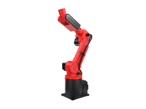
| BRTIRUS0805A | 5 kg | 990 mm | ±0.05 mm | Compact cells, smaller presses, sprue picking and light insert handling |
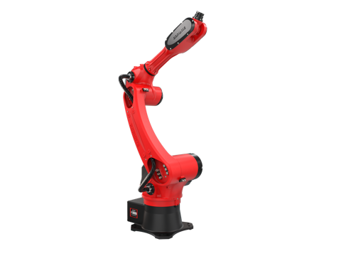
| BRTIRUS1510A | 10 kg | 1587 mm | ±0.05 mm | Larger presses, dual-function insert molding tools, longer reach into the mold area |
Both are six-axis platforms. Reach and payload are the two numbers that most often decide between them: a dual-function insert molding tool with a finished part on one side frequently pushes the tool-plus-part mass beyond what a 5 kg platform can carry with a safe dynamic margin, while a compact sprue picking cell on a small press may not need the reach of a larger arm.
Robot specifications are quoted from the manufacturer's selection documentation. Integration — tool design, mounting, signal handling, and cycle tuning — is where the cell is actually made to work.
Practical Integration Notes
Vacuum is not a grip; it is a seal. A vacuum cup holds a part only as long as the seal is maintained. Hot sprues, textured surfaces, and porous materials break the seal. If the sprue is hot and irregular, a light mechanical grip or a hybrid tool is often more reliable than vacuum alone.
Verify both sides of a dual-function tool. In insert molding, the cell fails in two ways: the insert is not held, or the finished part is not released. These need independent confirmation signals. A single "grip OK" signal is not enough.
Plan for flash and release agent. Molding environments deposit material on tools. Cups clog, jaws stick, and sensors false-trigger. Tool design should allow cleaning without disassembly, and sensors should be mounted where they are not directly in the flash path.
Match the tool to the mold, not the other way around. Insert pocket depth, sprue location, and ejection stroke are fixed by the mold. The tool must reach them; the robot must carry the tool. This order — mold, tool, robot — prevents the most expensive rework.
Confirm communication requirements early. The signals exchanged between the robot cell and the molding machine (mold open, ejector forward, part clear, insert seated) determine the I/O and protocol requirements. These should be confirmed against the specific controller and machine configuration rather than assumed.
FAQ
What is the difference between vacuum and mechanical gripping for sprue picking? Vacuum is simpler and lighter, but depends on a seal that hot, irregular, or porous sprues may not provide. Mechanical gripping is more tolerant of surface condition but adds mass and can mark soft material. Many cells use a hybrid approach: vacuum for the finished part, mechanical for the sprue.
How do I calculate the payload requirement for a dual-function insert molding tool? Add the tool mass, the insert mass, the finished part mass, and a dynamic margin for acceleration. The tool itself is often the largest single contributor. A tool that appears to fit within the robot's payload rating may still exceed it once the part and dynamic margin are included.
Can the same robot handle both sprue picking and insert loading? Yes, and this is common in insert molding cells. The tool is typically dual-function: one side handles the insert, the other handles the finished part or sprue. The robot must have enough payload for the combined tool and parts, and enough reach to enter the mold area safely.
What verification signals should a molding cell have? At minimum: part-present or grip confirmation on each side of a dual-function tool, insert-seated confirmation before mold close, and part-clear confirmation before the next cycle. These signals are exchanged with the molding machine and should be defined during cell specification, not after commissioning.
How does tool changeover affect cell design? If the cell runs multiple part numbers, a quick-change plate with integrated pneumatic and signal pass-through reduces changeover from hours to minutes. If the cell runs one part number for its life, a fixed tool is simpler and lighter.
What robot reach is needed for a typical molding cell? Reach is determined by the distance from the robot mounting position to the deepest point of the mold area, plus the tool envelope. A compact cell on a small press may need under 1000 mm; a larger press with a dual-function tool entering the mold area may need significantly more. Reach should be calculated from the actual cell layout, not estimated.
Are explosion-proof robots required in molding cells? Not typically. Explosion-proof variants exist for specific hazardous environments, but standard molding cells do not normally require them. If the process involves flammable release agents or solvents in the cell area, this should be confirmed against the specific site classification.
Where to Go From Here
If you are specifying an EOAT or gripper interface for a molding cell, the sequence that prevents rework is:
- Write down the part, the insert, and the sprue — geometry, weight, temperature, surface sensitivity.
- Write down the mold interface — pocket location, sprue location, ejection stroke, available clearance.
- Choose the gripping principle against the part, not the robot.
- Budget payload including the tool, not just the part.
- Define the verification signals before commissioning.
- Select the robot platform against the tool and the mold layout.
If you are working through a specific cell — insert molding, nut embedding, sprue picking, or a combination — our engineering team can review the tool concept, payload budget, and interface requirements against the actual mold and machine configuration. Integration scope, tool design, and communication requirements are confirmed per project.